EN
7
2.2
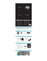
THE PARTS OF THE OZONE GENERATOR
Front view
Rear view
1. Air inlet
The fan draws in ambient air here. No ozone
exits the device here.
2. Timer display
This display shows the operating time set by
the user and the remaining operating time.
3. Timer setting button
This button is to set the period of operation.
4. On/off switch
This is the switch for the power supply.
5. and 6. Ozone output selector switches
These two switches set the ozone output to
10, 20 or 30G.
7. Power cable socket
The socket for the power cable plug.
8. Fuse drawer
This main fuse for the device is placed here.
It breaks in the case of a short circuit.
9. Ozone outlet
The air filled with ozone gas concentrate exits
the device here.
2.3
ELECTRICAL CONNECTION
THE GENERATOR CAN ONLY BE CONNECTED TO A 220
–
240V SYSTEM WITH
THE POWER CABLE PROVIDED FOR THE DEVICE. THE SYSTEM MUST HAVE A
GROUNDED WALL OUTLET!
1
2
3
4
5
7
8
6
The ozone generators in this series may only operate with dry ambient air. We do not
recommend using pure (100%) oxygen.
The warranty no longer applies when pure (100%) oxygen is used.
9
Summary of Contents for PRO 30000 TS
Page 32: ......


