background image

MAINTENANCE

OPERATION (cont.)

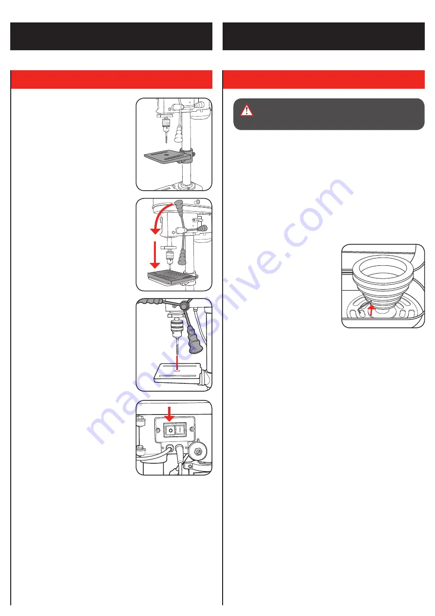
5.  GENERAL MAINTENANCE

1.   Ball bearings are packed with grease at the factory. No further 

lubrication of bearings is required.

2.  Lubricate all moving parts periodically. Wipe the column, table and 

base with an oily cloth to minimise corrosion.

3.  Keep air vents clean of dust and dirt.
4.  Remove dust and dirt from the drill press regularly with a soft cloth, 

brush or compressed air.

5.  If the power cord is damaged, have it replaced by an electrician or a 

power tool repairer.

6.  Regularly check that all bolts, screws and nuts are securely fixed as 

these could work loose during normal operation.

7.  If the drive belt will not align with 

the pulleys. The pulleys may be 

worn and need to be replaced. To 

remove the pulleys, use the 3mm 

allen key provided. Loosen in an 

anti-clockwise direction.

Note:

 Ozito Industries will not be 

responsible for any damage or injuries 

caused by the repair of the drill press 

by an unauthorised person or by 

mishandling of the drill press.

WARNING!

 ENSURE THE DRILL PRESS IS 

DISCONNECTED FROM THE POWER SUPPLY 

BEFORE PERFORMING ANY MAINTENANCE.

5.   Adjust the table to your desired 

position.

6.   Slowly rotate the feed wheel 

handles to bring the drill bit down 

towards the table and into your 

workpiece. After drilling a hole, 

release the feed wheel handles 

slowly to return the 13mm keyed 

chuck to its original position.

Note:

 Ensure the hole in the centre 

of the table is aligned with the drill bit. 

If not aligned, use the 4mm Hex key 

provided to loosen the head assembly 

on the column support and re-align the 

head assembly. Re-tighten the 2 head 

lock screws.

7.   Continue the operation until the  

task is completed. When completed, 

switch the drill press off by pressing 

the red (O) button on the switch. 

0

10

20

30

40

50

0

10

20

30

40

50

0

10

20

30

40

50

0

10

20

30

40

50

0

10

20

30

40

50

0

10

20

30

40

50

0

10

20

30

40

50

0

10

20

30

40

50

0

10

20

30

40

50

0

10

20

30

40

50

Summary of Contents for DP-350U

Page 1: ...rect installation a failure to follow the operating instructions for example connecting it to an incorrect mains voltage or current type or a failure to follow the maintenance and safety instructions or by exposing the device to abnormal environmental conditions or by lack of care and maintenance Damage to the device caused by abuse or incorrect use for example overloading the device or the use or...

Page 2: ...o the desired position 5 Lift the head assembly and slide it down onto the column as far as it will go To secure in position install the two head lock screw Tighten using the 4mm Hex key rotating in a clockwise direction 1 Pulley cover 2 Pulley cover knob 3 Feed wheel handles 4 Belt tension knob 5 Head lock screws 6 Feed wheel hub 7 Column 8 Table 9 Table support 10 Table support lock 11 Column su...

Page 3: ...w them into the feed wheel hub 7 To fit the 13mm keyed chuck first place a piece of timber on the table and position the 13mm keyed chuck with the jaws retracted under the drive shaft Raise the table toward the drive shaft until the 13mm keyed chuck is approximately 25mm from the drive shaft 8 To secure the 13mm keyed chuck to the drive shaft gently lower the drive shaft using the feed wheel handl...

Page 4: ...ti clockwise direction 2 Ensure the drill bit is secure in the 13mm keyed chuck and tightened correctly Lower the feed wheel handles to the desired depth using the depth scale 3 Whilst holding the feed wheel handles tighten the depth indicator lock nuts until they touch the metal stop 4 Lift the feed wheel handles up and then proceed to operate the drill press 5 To disable the depth lock loosen th...

Page 5: ... speed of the drill press can be changed by adjusting the belt on the pulley system Using a smaller pulley on the spindle chuck increases the drill speed Using a larger pulley on the spindle chuck decreases the drill speed 1 Loosen the belt tension knob 2 Push the motor towards the head assembly and tighten the belt tension knob 3 To adjust the belt speed move the belt to the correct pulley step f...

Page 6: ...ti clockwise direction Note Ozito Industries will not be responsible for any damage or injuries caused by the repair of the drill press by an unauthorised person or by mishandling of the drill press WARNING ENSURE THE DRILL PRESS IS DISCONNECTED FROM THE POWER SUPPLY BEFORE PERFORMING ANY MAINTENANCE 5 Adjust the table to your desired position 6 Slowly rotate the feed wheel handles to bring the dr...

Page 7: ...ced in the 13mm keyed chuck Remove the drill bit and reinsert correctly ensure the chuck jaws are fully tightened The 13mm keyed chuck is not installed correctly Ensure you install the 13mm keyed chuck correctly Drill bit binds in workpiece Belt tension is set incorrectly Re adjust the belt tension DESCRIPTION OF SYMBOLS SPARE PARTS V Volts Hz Hertz Alternating current W Watts min Revolutions or r...

Page 8: ...ons to operate the power tool Power tools are dangerous in the hands of untrained users e Maintain power tools Check for misalignment or binding of moving parts breakage of parts and any other condition that may affect the power tool s operation If damaged have the power tool repaired before use Many accidents are caused by poorly maintained power tools f Keep cutting tools sharp and clean Properl...

Reviews: