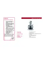
4. LOCKING PLATE ASSEMBLY
5. TIPPING HANDLE & MOTOR ASSEMBLY
2. Slide the locking plate over
the large diameter shaft at
the support leg end of the
frame assembly. Ensure
the plate is correctly
aligned with the bearing
bracket and clear of the
circlip.
3. Insert the M10x70
bolt with washer and
secure with washer
and nut. Tighten with
17mm spanner (not
supplied).
Note:
Ensure the tipping
handle easily pivots
on the large shaft so
that the locating pins
can be engaged and
disengaged.
2. Insert the M8x16 bolt and spring into the tube of the tipping handle.
Engage the locating pins into the locking plate and use this as a
lever to compress the spring against the large shaft.
1. Use assembly
fasteners bag
1. Use assembly
fasteners bag
4. Use assembly
fasteners bag
3. Insert the 2 M8x30 hex bolts,
spring washers and washers.
Secure with nut from rear of
bearing bracket. Tighten with
13 & 14mm spanners (not
supplied).
2
4
2
2
2
6
4
M8 55
M8 65
M8 60
M8 20
M8 20
M8 30
M8 20
1
M10 70
2
10
2
4
M8 16
1
1
2
M8 25
4
4
4
8
Bolt
Spring
M8 x 25
M8 x 20
E
F
G
2
4
2
2
2
6
4
M8 55
M8 65
M8 60
M8 20
M8 20
M8 30
M8 20
1
M10 70
2
10
2
4
M8 16
1
1
2
M8 25
4
4
4
8
2
4
2
2
2
6
4
M8 55
M8 65
M8 60
M8 20
M8 20
M8 30
M8 20
1
M10 70
2
10
2
4
M8 16
1
1
2
M8 25
4
4
4
8
5. Slide the motor and
motor housing over
the pinion shaft lining
up the key ways.
Secure the motor and
motor housing to the
frame with the bolts,
spring washers and
washers. Tighten with
14mm spanner (not
supplied).