Praktika T-04(K) speedgate
12
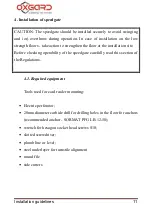
4.2. Installation of speedgate
CAUTION! We recommend to mark the mounting holes corresponding to
side unit base holes when the wings are already installed.
CAUTION! During installation take into account that glass wings cannot
be adjusted. It is recommended to check the correctness of installation
before fixing the side units.
CAUTION! During preparation of the installation site take into account
that each side unit requires a separate power supply.
CAUTION! During installation of the speedgate prepare conduits for cable
routing of CAN-bus to connect side units
4.2.1.
Prepare horizontal surface at the installation site of
speedgate.
4.2.2.
Prepare conduits or cable channels from the site to the
installation site of PU, RC, as well as, if required, to the point of ACS
connection and FA.
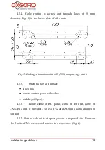
4.2.3. Follow the layout and drill 12 holes of 20mm diameter for
floor anchors. Location of mounting holes related to the outer
dimensions of the speedgate and its dimensions are shown in Appendix
4. Depth of the hole should exceed the length of the anchor for more than
5mm. Put anchors in the holes.


