8
The control station is pre-assembled and leak tested
at works.
The pump and the electric sensor attachment to pipe
are cabled and joined to the connection cable via the
plug-in connector.
The control station is supplied for left hand side con-
nection.
For right hand side connection, turn the complete con-
trol station vertically. Now turn pump in such a way
that the motor is pointing forward. Loosen collar nuts
at the pump. Turn pump by 180° and re-tighten collar
nuts firmly.
Screw control station firmly onto the stainless steel
distributor/collector.
When
installing
the
distributors/collectors with 2 and 3 heating circuit con-
nections, mount the bracket supplied with the control
station as additional bracket (see illustr. 5.1 and part
6, illustr.6.1).
When mounting the control station inside a cabinet,
please observe paragraph 4.2 “Dimensions/connection
size”.
To mount the temperature controller (part 3, illustr. 6.1),
remove the protection caps of the three-way valve.
Fix the sensor attachment to pipe (part 2, illustr. 6.1)
onto the body of the supply using the elastic fastening
strap (part 4, illustr. 6.2). Set sensor for attachment to
pipe about 5 K above the nominal value of the maxi-
mum flow temperature.
Connection to the sensor attachment to pipe, via the
pre-assembled cabling, is carried out by plugging it
into the pump plug.
The power supply must be switched off before
work commences.
Observe warning advice under paragraph 2
(safety notes)!
– Do not use any lubricant or oil when installing
the valve as these may destroy the seals. If ne-
cessary, all dirt particles and lubricant or oil re-
sidues must be removed from the pipework by
flushing the latter.
– When choosing the operating fluid, the latest
technical development has to be considered (e.g.
VDI 2035).
– Please protect against external forces (e.g. im-
pacts, vibrations etc.).
After installation, check all installation points for le-
aks.
7 Operation
7.1 Bleeding the system
Before initial operation, the system must be filled and
bled with due consideration of the permissible opera-
ting pressures.
7.2 Correction factors for mixtures of water and
glycol
The correction factors of the manufacturers of the an-
tifreeze liquids have to be considered when setting
the flow rate.
8 Accessories
The Oventrop ball valves:
– 1406383 DN 20 G
3
⁄
4
F x G1 M
– 1406384 DN 25 G1 F x G1 M
can be screwed onto the control station for the isola-
tion of the supply and the return pipe.
9 Maintenance
The control station is maintenance-free.
10 Warranty
Oventrops warranty conditions valid at the time of
supply are applicable.
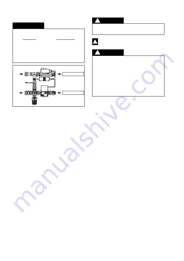
– The supply at the control station is always loca-
ted at the top and the return at the bottom.
This must be strictly observed when installing
the distributors (see illustr. 6.2)!
– The installation and operating instructions of the
stainless steel distributors/collectors “Multidis
SF” must be observed.
Illustr. 6.2 Flow direction
6.2 Installation of “Regufloor H”
Supply distributor
Return collector
Supply
Return
DANGER
!
PRECAUTION
!
ATTENTION
!


