otometrics madsen itera ii Reference Manual Download Page 93

dB

Hz

40

1000

Press STORE...

...continues at

40

1500

Press STORE...

...continues at

40

2000

Press STORE...

...continues at

40

3000

Press STORE...

...continues at

40

4000

Press STORE...

...continues at

40

6000

Press STORE...

...continues at

40

8000

Press STORE...

...continues at

40

12500

Press STORE...

...continues at

40

1000

Press STORE...

...continues at

40

750

Press STORE...

...continues at

40

500

Press STORE...

...continues at

40

250

Press STORE...

...continues at

40

125

Press STORE...

...continues at

40

1000

Press STORE...

...continues at

40

1500

Press STORE...

14 DB LEV.
NEW TRA.

Choice of initial volume level for a new transducer, or change between different tests.

NO CHANGE

or adjustable in the range: -10 to 50 dB

15 DB LEV.
NEW FREQ

Choice of initial intensity when changing frequency.

NO CHANGE

(the frequency remains the same) or adjustable in the range -10 to 50 dB.

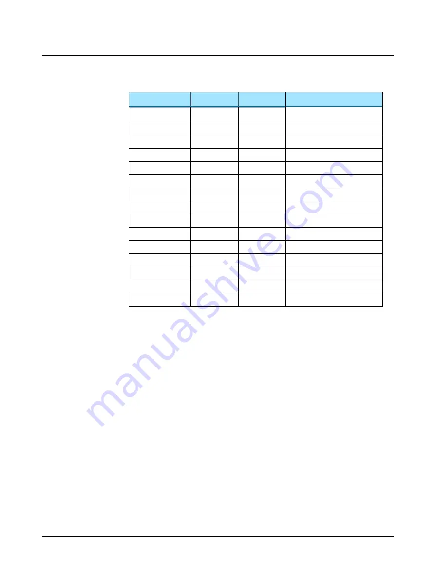
See the example (with setting 13 set to

WRAP

):

Otometrics - MADSEN Itera II

93

10 Setup of parameters

Summary of Contents for madsen itera ii

Page 1: ...MADSEN Itera II Reference Manual Doc No 7 50 0860 EN 26 Part No 7 50 08600 EN ...

Page 2: ...tometrics the Otometrics Icon AURICAL MADSEN Otoscan ICS and HORTMANN are registered trademarks of Natus Medical Denmark ApS in the U S A and or other countries Version release date 2019 06 11 214086 Technical support Please contact your supplier Otometrics MADSEN Itera II 2 ...

Page 3: ...Extended range 19 3 2 8 Change Ear L R 20 3 2 9 Setup 20 3 2 10 Talk back 20 3 2 11 Masking 20 3 2 12 dB steps 21 3 2 13 Microphone 21 3 2 14 Talk over 22 3 2 15 Response indicator 22 3 2 16 Start Pause Stop 22 3 2 17 Store toggle threshold status 23 3 2 18 Stimulus masking intensity knobs 23 3 2 19 Stimulus speech count buttons 24 3 2 20 Frequency 25 3 2 21 Erase 25 3 2 22 Xmit 26 3 3 Socket conn...

Page 4: ... 5 1 Preparing the test environment 53 5 2 Preparing the test equipment 53 5 2 1 Connecting the cables of the test equipment 54 5 2 2 The patient responder 54 5 2 3 Preparing for air conduction testing 55 5 2 4 Preparing for bone conduction testing 55 5 2 5 Preparing for testing with masking 56 5 3 Listening check 56 5 4 Preparing the client 56 5 4 1 Hygienic precautions 57 5 4 2 Inspecting the cl...

Page 5: ... Fowler test 77 8 5 STENGER Test 78 8 6 Hearing Instrument Simulation HIS 79 8 6 1 The HIS procedure 79 8 6 2 Viewing thresholds and filters 81 8 6 3 Manually adjusting the HIS filters 82 8 7 Overview of monaural binaural test signals and the masking side 84 9 Managing Data and Results 85 9 1 Transferring test results from the audiometer to the PC 85 9 2 Storing data 85 9 3 Printing results 85 10 ...

Page 6: ...nd output sockets 109 App 0 2 RS232 interface sockets 109 16 Maximum output levels 111 16 1 Tone 111 16 2 NBN 111 17 Abbreviations 113 18 Standards and safety 115 18 1 Symbols used 115 18 2 Warning notes 115 18 3 The OTOsuite Audiometry Module 117 18 4 Manufacturer 117 18 4 1 Responsibility of the manufacturer 117 19 Technical specifications 119 19 1 MADSEN Itera II 119 19 2 Accessories 123 19 3 N...

Page 7: ...s There are three output options standard headphones AC bone conductors BC special output SF which can be connected for instance to a free field loudspeaker or insert phone see available out put in SETUP items 89 MADSEN Itera II can be calibrated for several types of headphones simultaneously Transferring data to and from a pc The test results are stored in the device even when it is switched off ...

Page 8: ...DSEN Itera II and the Audiometry module Users audiologists ENTs and other health care professionals in testing the hearing of their patients Use diagnostic and clinical audiometric testing 1 3 About this manual This is your guide to installing calibrating and using MADSEN Itera II and to using the OTOsuite Audiometry Module It also introduces you to the key features of the device and the software ...

Page 9: ...tes 1 4 Typographical conventions The use of Warning Caution and Note To draw your attention to information regarding safe and appropriate use of the device or software the manual uses pre cautionary statements as follows Warning Indicates that there is a risk of death or serious injury to the user or patient Caution Indicates that there is a risk of injury to the user or patient or risk of damage...

Page 10: ...1 Introduction to MADSEN Itera II 10 Otometrics MADSEN Itera II ...

Page 11: ...es required To connect the accessories see Installation 105 Connect the Patient Response Switch Connect headphones insert phones If bone conduction is required connect the bone conductor Connect external and Free Field microphones if required Configuring the OTOsuite Audiometry Module See see Configuring the Audiometry Module 101 Preparing for testing Before you receive the client and start the se...

Page 12: ...hown on the display 4 Press STORE 5 Turn Itera II off and then on again It now remembers your preferred settings Shortcuts A number of functions in Itera II can be activated by a shortcut so that you just have to press and hold the appropriate but ton and turn the knob For a full list of shortcuts see Temporary changes in the setup 88 Example 1 Press the SPEECH button to select Speech mode 2 Press...

Page 13: ...m the front panel See Front panel con trols 15 3 1 Display A Test signal indicator B Audiogram symbols C Stored threshold D Ear indicator E Function key markers During start up the display briefly shows information regarding the device type and version followed by the test screen last used The abbreviations used on the display are explained in Abbreviations 113 Top line During Tone testing the upp...

Page 14: ...ng If masking for the contralateral ear is enabled this is shown on the opposite side Symbols used Left ear Response No response Right ear Response No response Air unmasked Air masked Bone mastoid unmasked Bone mastoid masked Sound field unmasked binaural applies to both ears Sound field masked UCL UnComfortable Loudness level MCL Most Comfortable Loudness level 14 Otometrics MADSEN Itera II 3 Ove...

Page 15: ...ome buttons have a light to indicate whether the function is currently active or not Press the button to activate Press the button again to deactivate 3 2 1 Front panel layout The MADSEN Itera II buttons and controls are grouped according to their function and how frequently they are used The buttons and knobs most frequently used are placed directly below the display Otometrics MADSEN Itera II 15...

Page 16: ... 22 M Response indicator 22 N Start Pause Stop 22 O Store toggle threshold status 23 P Stimulus masking intensity knobs 23 Q Stimulus speech count buttons 24 R Frequency 25 S Erase 25 T Xmit 26 Beep If you try to use a button which is not enabled you will hear two short beeps MADSEN Itera II also beeps when the SISI test is completed 3 2 2 Test column Press to select the test 16 Otometrics MADSEN ...

Page 17: ...ity Index 75 ABLB Alternate Binaural Loudness Balance 77 STENGER Test 78 Hearing Instrument Simulation HIS 79 Current test settings When you switch to a new test the current setting of the test that you are leaving will be saved and re established when you return to the test 3 2 3 Transducer column Press to select the output transducer AC Selects the Air Conductor BC Selects the Bone Conductor SF ...

Page 18: ...d of time Impulse shortcut functions Test signal duration To change the duration of the test signal turn the Right level selector while you press and hold IMPULSE 3 2 5 Input MIC CD REVERSE MIC Press MIC to select the signal from external or internal microphone input The internal microphone is loc ated below the display External microphones are for instance the goose neck microphone or if you are ...

Page 19: ... of stimuli above the safety limit approx 100 dB The safety limit is set to 20 dB below the maximum dB HL for a given transducer and frequency The exception is at 125 Hz where the limit is 30 dB below the maximum dB HL Extended Range has three modes to select see SETUP SETUP items 89 Auto All levels at all frequencies are always accessible but the Extended Range button is lit when a level above th...

Page 20: ...rs 87 This serves to prevent accidental changes in the setup SISI Press SETUP to enable the number of small increments to be changed using the right LEVEL selector Fowler ABLB Press SETUP to enable changing the frequency of the alternating tone using the right LEVEL selector 3 2 10 Talk back The patient s speech is always fed back to the operator s monitor headphone You can remove the signal by lo...

Page 21: ...er and if applicable the serial no appear in the display The transducer button flashes and you can then select a different masking trans ducer by pressing one of the three TRANSD buttons AC BC or SF Masking noise in Speech Select the masking ear press and hold MASK ON and press L R to toggle between left right and both ears 3 2 12 dB steps Choose between the following attenuator steps 1 dB 2 5 dB ...

Page 22: ...X displayed and a talkover level related to a mean of the saved thresholds THR for the following frequencies 250 500 1000 2000 and 4000 Hz MIC sensitivity Right LEVEL selector Sets Mic sensitivity Talkover signal to head phone Left Right arrow button Controls the Talk Over signal to the right or left headphone Press twice to transmit the signal to both ears The change over from INTERN to EXTERN oc...

Page 23: ...ntensity at which a threshold value has previously been found this value is shown in the display by means of an symbol beside the frequency indication and the applicable audiogram symbol beside the level indication depending on the selection of ear masking and transducer type 3 2 18 Stimulus masking intensity knobs Left Level knob Intensity change Changes the intensity for the stimulus signal rega...

Page 24: ...peech testing Word counting method speech Choice of word counting method for speech testing Alternating Fowler fre quency Alternating Fowler frequency Master volume HIS Master volume value selection in HIS Parameter selection SETUP Parameter selection in SETUP Power out voltage DC POWER OUT voltage 3 2 19 Stimulus speech count buttons Left INT button FAIL Presentation of test signal This function ...

Page 25: ...exception is 125 Hz which follows the setting in SETUP SETUP items 89 FREQUENCY shortcut functions Display graphs HIS mode If you turn this knob in HIS mode various graphs will be shown see Hearing Instrument Sim ulation HIS 79 3 2 21 Erase Note Switching off the power does not erase stored thresholds from the memory This button has several functions Deleting all audiogram data You must delete all...

Page 26: ...EN Itera II A SF AC right and left B AC C BC D CD Tape E External microphone Monitor headset F Monitor G Talk back H Digital aux I Patient response J DC power out K RS232 interface Socket Description A SF AC Connection for the SF Transducer output Here you can connect any headphone or free field system Connect the blue 1 4 jack plug for left SF Left and the red 1 4 jack plug for right SF Right B A...

Page 27: ...onnected to EXTERNAL MIC MONITOR HEADSET G TALK BACK Connection for the Talk Back microphone for communication from patient to operator Set the switch on the Talk Back microphone to ON H DIGITAL AUX N A I PATIENT RESPONSE Connect the black 1 4 jack plug from the Patient Response switch When the patient presses the Patient Response switch this lights the RESPONSE indicator light and gives an audibl...

Page 28: ...for all electrical equipment used in the proximity of the client that The connected equipment must comply with Medical Electrical Systems in IEC 60601 1 3 1 edition 2012 For information on how to use the device with a PC see Managing Data and Res ults 85 Supply voltage connection 100 120 V AC 200 240 V AC 50 60 Hz 60 VA Fuses 2 T 1 A H 250 V 5 mm 20 mm Before you replace a fuse first switch off th...

Page 29: ...atures below are device dependent With the Audiometry Module you can perform testing while you follow stimulus settings and test progress on your PC display view and print test results view historic audiometry results from NOAH view online audiometry results during testing use the Masking Assistant to prompt when masking is recommended view the masking level indicator in audiogram view audiogram o...

Page 30: ...new audiogram You will be prompted to save or cancel current data 4 2 2 Edit menu Menu item Shortcut Description Audiometric prop erties Ctrl U Click to enter Tester name Test Date and air conduction transducer for a manu ally entered audiogram Note The air conduction transducer is stored when you have selected it in the transducer section of the Control Panel or with device controls if applicable...

Page 31: ...or both a left and a right audiogram on your screen Combined View Click to view both ears in a single audiogram Split View Click to view separate audiograms for each ear Left Right Click to display the left ear audiogram on the left side of the window and the right ear audiogram on the right side of the window when Dual Graph View is enabled in Options Audiometry Tone Misc Right Left Click to disp...

Page 32: ...ves and Symbols dialog box This dialog box and its related function are specific to configuring the curves and symbols to be displayed on the audiogram or speech graph during testing See Curves and symbols selection 42 Options See description of how to work with user options and User Tests in the OTOsuiteUser Guide Additional icons Menu item Description Import Audiometry Data Click to import audio...

Page 33: ...rted transducer was stored with the data The Masking Assistant is a tool provided to help you with an indication that there may be frequencies where testing with masking1 is recommended The audiogram symbol will flash at the specific frequencies where contralateral masking may be recommended2 1 Katz J Lezynski J 2002 Clinical Masking In J Katz ed Handbook of Clinical Audiology Williams and Wilkins...

Page 34: ...thresholds measured without masking are checked Levels which did not evoke a response are excluded from the check This means that as soon as a masked threshold has been stored the flashing stops for that frequency denotes configurable Air Bone gap criterion Tools Configuration Wizard Audiometry Configure Masking Assistant Min IA is frequency specific These are the Min IA tables for TDH 39 and Otom...

Page 35: ... Agnew BJA 1999 500 64 Munro Agnew BJA 1999 750 60 N A traditional value 1000 58 Munro Agnew BJA 1999 1500 60 N A traditional value 2000 56 Munro Agnew BJA 1999 3000 58 Munro Agnew BJA 1999 4000 72 Munro Agnew BJA 1999 6000 54 Munro Agnew BJA 1999 8000 62 Munro Agnew BJA 1999 4 5 The Audiometry Module Control Panel Click the Control Panel icon in the toolbar to activate the Control Panel Note The ...

Page 36: ...I automatically connects to the audiometer Note You cannot operate MADSEN Itera II from the Control Panel The Control Panel is divided into a number of sections where you can view various settings and a section for controlling communication with the audiometer 36 Otometrics MADSEN Itera II 4 Navigating in the OTOsuiteAudiometry Module ...

Page 37: ...the audiometer or in OTOsuite 4 6 The stimulus bar A Intensity B Stimulus indicator C Transducer indicator D Stimulus being presented E Frequency F Stimulus bar color G Routing indicator H Masking on Intensity Indicated by the dB level above the channel status bars Masking is denoted by square brackets around the level calibrated in effective masking level The green triple wave symbol above the le...

Page 38: ...that will be displayed on the audiogram s when a data point is stored The symbol shown reflects the current audiometer measurement settings See also Curves and symbols selection 42 Frequency Indicated by the Hz value in the center of the stimulus bar 4 6 2 The Speech stimulus bar A VU meter B Speech score C Word count During online testing the stimulus bar shows 38 Otometrics MADSEN Itera II 4 Nav...

Page 39: ...esents the level actually being delivered to the patient 4 7 The Tone test screen During online testing the screen reflects the test done by the audiometer as it progresses A Stimulus bar B Work area C Legend box 4 7 1 The work area in the Tone screen The Tone test work area consists of a range of elements for viewing and selecting various features The audiogram 40 With a description of audiogram ...

Page 40: ...where you place the mouse The color indicates the routing Blue left Red right Black binaural Audiogram Intensity is shown to the left of the audiogram in dB HL Octave frequencies are shown below the audiogram in Hz Interoctave frequencies are shown above the audiogram in Hz Viewing the audiogram You can choose between 40 Otometrics MADSEN Itera II 4 Navigating in the OTOsuiteAudiometry Module ...

Page 41: ...espond to your viewing preference 1 Select Tools Options Tone Misc Dual Graph View or in the menu bar under View A Stimulus marker ear color B Masking level indicator Viewing masking levels Masking levels Below the audiogram the intensity levels used for masking can be displayed It is an option to display the masking levels Select Tools Options Tone View Misc Masking Levels In combined view the no...

Page 42: ...dition The current symbols and line style are shown 3 Double click on the symbol you wish to change The Symbols selection dialog box is shown 4 Double click on the symbol you wish to use 5 To change the line style of the curve select from the Line Style drop down list 6 To change the color double click on the current Color square Select a new color or click on Define custom colors to select a colo...

Page 43: ...s file select all elements in the drawing including the invisible outer frame as well as the symbol itself centered within the frame Right click and select Save as picture 5 Name the file and select the file type emf 6 Save it in C Program Files GN Otometrics OTOsuite AudSymbols 7 Launch the OTOsuite Audiometry Module and select Tools Curves and Symbols The new symbol should appear on the list of ...

Page 44: ...rves selec ted in the list 4 If you decide to make a new audiogram then a new Current audiogram is generated in the Compare Audiograms fea ture box list and what was previously the current audiogram consequently becomes a historical one displayed with measurement date 5 If you deselect the viewing of a Current audiogram so that it is no longer shown then it will instantly be reselected if you try ...

Page 45: ...ds at their approx imate dB level e g bird plane Severity Displays the audiometric severity levels normal mild moderate moderate to severe severe profound Speech Banana Displays the speech banana of a listener with normal hearing Speech Letters Displays speech sounds at their approximate dB level Unusable area Shades the area which is outside the patient s dynamic range of hearing Otometrics MADSE...

Page 46: ...n the screen 4 8 2 Ear shift frequency and level setting When you change test ear you can define that the frequency and level should be set to 1000 Hz at 20 dB HL To do so select Tools Options Tone Measurement Ear Shift Frequency and Level Check Ear Shift Frequency and Level 4 9 The Speech test screen During online testing the screen reflects the test done by the audiometer as it progresses A Stim...

Page 47: ...ction as well as the articulation index To configure pure tone average PTA calculation select Tools Options Audiometry Gen eral Misc PTA Frequency AC BC The AI is calculated according to the Count the dot method Stenger Displays the results of a speech Stenger test optional Scoring options are positive or negative 4 9 3 Terms and abbreviations used in Speech testing SDT Speech Detection Threshold ...

Page 48: ...pe ear transducer stimulus type routing and speech material If you wish to make manual changes on the fly use the control panel to select The predefined tests are incorporated as rows in the speech table To select a predefined test simply click the button in the Test colum This will load all the speech settings and speech material If you perform a test which is not available in a predefined Speech...

Page 49: ... are color coded according to their respective routing The legend adapts to the tests and adds a row for each measurement you make You can also pin tests so that they are readily available for future testing Adaptive rows The rows in the adaptive legend always show the current measurement settings and the measurements you have made A new row will be added to the legend every time you make a new te...

Page 50: ...n identical test To edit a pinned test make sure that User Tests are not write protected in the Configuration Wizard To pin a row simply select the row right click and select Pinned Tests Pin Test Here you can also rearrange pinned rows by moving them up or down in the legend Modifying Click n Get for a pinned test You can assign a different speech stimulus and or transducer to a pinned test This ...

Page 51: ... the actual test with a different word list Use Click n Get to load the desired starting point and simply switch to any word list you wish to use after the familiarization Storing data in a row To store data in a row click the dB field in the relevant row or press S on your keyboard The Info field The Info field provides additional information such as a stimulus source e g CD Live File or specific...

Page 52: ...4 Navigating in the OTOsuiteAudiometry Module 52 Otometrics MADSEN Itera II ...

Page 53: ...hen the stimulus will be presented For pediatric testing consider using a highchair which is a familiar environment for most children and will place them closer to eye level with the visual reinforcement toys Make sure if performing visual reinforcement audiometry that the reinforcing toys can be seen by the child A child cannot look over and up at a toy until approximately 9 months of age Lightin...

Page 54: ...e patient in a sound booth if one is available and facing away from MADSEN Itera II Instruct the patient in how to use the patient responder Instruct the patient in pressing the button even if only weak signals are heard Note During automatic testing if the patient presses the switch repeatedly during a stimulus presentation the response is ignored Note During automatic testing if the patient does...

Page 55: ...onductor on the patient Instruct the patient in what you are about to do Note The bone conductor cable and insert phone cable must not be removed or tampered with while MADSEN Itera II is powered on Either disconnect the bone conductor or insert phone entirely from the instrument or make sure that the instrument itself is disconnected from the power source If a sound booth is not available place t...

Page 56: ...be hearing a noise in the other ear The tones can be heard in either ear The patient should respond to the tones in the test ear and ignore the noise The patient should press the patient response switch as soon as the tone is heard You may prefer that the patient raises a hand to indicate in which ear the tone was heard This is particularly relevant since masked testing is used to determine that t...

Page 57: ...ad 3 Inspect the ear canal and make sure that you can see the ear drum If you can see apparent narrowing of the ear canal it may be blocked by vernix or debris or it may not be straight 4 If the ear canal is blocked for instance by vernix or debris the outcome of the procedures may be affected Clean the ear canal if required 5 5 Preparing the Audiometry Module for testing MADSEN Itera II and the A...

Page 58: ... if the headphones are comfortable 4 Tighten the headband while holding the headphones in place with your thumbs 5 Examine the placement of the headphones to make sure they are level and properly positioned Insert Earphones Young children tolerate insert earphones better than headphones The insert earphones are color coded the blue indicator for the left ear the red indicator for the right ear 1 S...

Page 59: ...of the bone oscillator securely on the boniest portion of the mastoid without any part of the transducer touching the external ear 2 Make sure the bone oscillator is tight on the mastoid but still comfortable 3 If you are going to perform masking with earphones position the other end of the bone oscillator headband over the patient s temple on the opposite side of the head so that the headband of ...

Page 60: ...5 Preparing for testing 60 Otometrics MADSEN Itera II ...

Page 61: ...one to the patient for 1 to 1 5 seconds 2 Use the corresponding LEVEL knob to set the intensity to approx 20 dB above the patient s presumed threshold If the patient does not respond to the presented signal turn the LEVEL knob to increase the signal level in steps of 10 dB until the patient responds 3 Reduce the signal level by 20 dB until the patient does not respond to the signal 4 Increase the ...

Page 62: ...ducer and Free Field speakers F F are assigned as transducers SETUP SETUP items 89 the results are stored as an individual threshold curve using the applicable Sound Field symbols Display 13 The symbol used for Sound Field applies to both ears unless masking has been used Tip If ear specific data is retrieved by blocking the contra lateral ear activate the masking on the audiometer to use the cor ...

Page 63: ... the test signal Other familiarization procedures may be preferred If you intend to test both ears test the better ear first If this is unknown start with the right ear Press L R to select the ear you wish to test 6 2 1 Testing 1 Press the INT button right or left to present the tone to the patient for 1 to 1 5 seconds 2 If the patient does not respond to the presented signal turn the LEVEL knob t...

Page 64: ... with masking applied to the better ear If the appliance of masking is to be optimally administered without using unnecessary masking it is recommended in the literature not to use the one number fits all 40 dB criterion for circum aural and 55 to 60 dB criterion for insert phones This may cause errors and will increase the test time as well as increase the strain on the patient Instead the litera...

Page 65: ...he closest 5 dB step Min IA TDH 39 Hz dB Source 125 35 Katz Lezynski 2002 250 48 Munro Agnew BJA 1999 500 44 Munro Agnew BJA 1999 750 40 N A fulfill traditional approach 1000 48 Munro Agnew BJA 1999 1500 40 N A fulfill traditional approach 2000 44 Munro Agnew BJA 1999 3000 56 Munro Agnew BJA 1999 4000 50 Munro Agnew BJA 1999 6000 44 Munro Agnew BJA 1999 8000 42 Munro Agnew BJA 1999 Min IA EAR 3A H...

Page 66: ...ter each increase present the tone no more than twice The tone is considered heard if the patient responds at least once If the tone is heard when the masking level has been increased with at least three 5 dB steps the so called masking plateau has been reached and the test tone level is considered the masked hearing threshold level 5 If the tone is not heard when the masking level is increased in...

Page 67: ...fter each increase present the tone no more than twice The tone is considered heard if the patient responds at least once If the tone is heard when the masking level has been increased with at least three 5 dB steps the so called masking plateau has been reached and the test tone level is considered the masked hearing threshold level 6 If the tone is not heard when the masking level is increased i...

Page 68: ...6 Tone testing 68 Otometrics MADSEN Itera II ...

Page 69: ...phone or CD input by pressing the MIC or CD button MIC If you press MIC the microphone selection is shown briefly in the display as follows EXTERN MIC or INTERN MIC The display then shows the selected microphone input for the current ear MIC1 default or MIC2 You can set the sensitivity independently for MIC1 and MIC2 Adjusting input sensitivity 70 regardless of whether both MIC input channels are ...

Page 70: ... you wish to operate MADSEN Itera II as a one channel or a two channel speech audiometer select either the same input to both ears one channel or select two different inputs two channel When you use two channel testing there are 16 possible combinations of inputs Regular one channel monoaural testing default CD_1 is the default input channel for right or left ears Masking is available for the oppo...

Page 71: ...mportant Be careful not to change the dB level before you have made a note of the results 7 1 4 Interrupting the speech signal You can interrupt the speech signal by deactivating the REVERSE button Note There are no interrupt buttons in Speech mode since they are used for counting words 7 2 Binaural Speech testing In binaural Speech testing a stimulus is presented to both ears either as a single s...

Page 72: ...ctor to adjust the strength of the input signal in the channel which is flashing on the display 2 Press L R to toggle to the opposite input channel to be able to adjust its sensitivity To calibrate the speech sig nal the VU meters must move into line with 0 dB on the VU meter scale Caution You should only use speech materials with a stated relationship between the level of the speech signal and th...

Page 73: ...able this setting press twice on L R When the masking signal returns to normal contralateral masking i e when you press MASK OFF or press L R the arrow s disappears 7 3 3 Binaural Speech with masking 1 To switch on masking noise press MASK ON MASK LOCK cannot be selected 2 By default masking noise is transmitted to both ears but you can select the masking ear press and hold MASK ON and press L Ron...

Page 74: ...7 Speech testing 74 Otometrics MADSEN Itera II ...

Page 75: ... and co workers Jerger Shedd and Harford 1959 and was introduced as a pro cedure that was reliable and reasonably objective The test consists of superimposing brief bursts of 1 dB intensity increments on a sustained tone presented monaurally through earphones at a sensation level of 20 dB at each tested frequency The patient is instructed to report any jumps in loudness detected while listening to...

Page 76: ...ess select Yes to erase data The counter is reset to zero and the test will start again from the beginning Changing the dB level To change the dB level use the left LEVEL knob Changing the dB increments To change the dB increments use the Right level knob 0 25 5dB If you do so while the test is in progress the counters are reset to zero and the test starts again from the beginning Changing number ...

Page 77: ...he intensity for Right and Left channel and the test name The frequency of the test tone and the rate of alternation from ear to ear and back again the alternating frequency appear in the bottom line Changing alternating frequency To change the alternating frequency 1 Press SETUP once and use the Right level knob 0 25 2 5 Hz 2 Press SETUP again to implement the new setting 3 You can present the si...

Page 78: ...nd right ears 2 To select the Stenger test press SPECIAL one or more times until STEN appears 3 Select the test by pressing STEN once The following display appears A tone is transmitted at the same frequency on the left and right sides simultaneously The display shows the signal selected as stimulus This is either TON WRB or NBN To change the stimulus see Changing stimulus 78 4 Press either of the...

Page 79: ... of the audiogram slope in dB octave is calculated and the HIS is set to about half this approximated slope according to half gain rule using either 6 dB less steep slope 12 dB medium steep slope or 18 dB steep slope 3 The frequency where the most amplification is wanted 4 kHz is the highest available is identified and the cut off fre quency is set accordingly 4 A gain is set to approximate half t...

Page 80: ...rmal speech considered for a person with normal hearing is around 65 dB SPL Alternately See Adjust HIS reference level 80 1 To start the simulation press START STOP Adjust HIS reference level Adjust the HIS reference level The level for normal speech considered for a person with normal hearing is around 65 dB SPL 1 Press SETUP once to view the Reference Level for instance 65 dB 2 To change this Re...

Page 81: ...filter is activated A Master volume B No filter activated C Filter activated Adjusting HIS Master Volume Note The system automatically sets the Master Volume Increasing the output level manually You can manually increase the output level by adding to the Reference Level Use the right and leftLEVEL knobs to change the Master Volume as follows The Master Volume for left and right ears are locked tog...

Page 82: ... the left or right ear press either the left or right INT button The filter characteristics for the selected ear are shown The top line shows the selected ear whether the currently displayed parameters apply to the filter for low pass LP or high pass HP The second line shows the filter s 3 dB cut off frequency the filter slope in dB per octave the asymptotic amplification at the filter cut off fre...

Page 83: ...to continue the procedure Filter examples Any filter whose amplification is set to 0 dB has no effect Fig 2 Low pass filter graph Fig 2 83 shows a graph where the characteristics of a low pass bass filter are set to an amplification of 20dB for frequencies under 250 Hz Fig 3 High pass filter graph Fig 3 83 shows a graph where the characteristics of a high pass treble filter are set to an amplifica...

Page 84: ...t signals and the masking side Test signal Masking signal Monaural Binaural Ipsi Contra THR X X SPEECH X X X X SISI X X ABLB X STEN X HIS X Fig 4 Monaural binaural test signals and masking side 84 Otometrics MADSEN Itera II 8 Special tests ...

Page 85: ...lts Follow the onscreen instructions 9 2 Storing data You can store one set of AC data and one set of BC data including thresholds for each frequency You can delete these thresholds one by one or collectively You can transfer these data to a PC with the OTOsuite Audiometry Module 9 3 Printing results From the PC you can print audiograms that have been saved in the OTOsuite Audiometry Module Otomet...

Page 86: ...9 Managing Data and Results 86 Otometrics MADSEN Itera II ...

Page 87: ...he left LEVEL knob to select the parameter item you wish to change When you select a new item the item number is displayed briefly in the bottom line for instance Item 5 As a rule the top line in the display contains a description of the current parameter for instance SF TRANSDUCER The bottom line contains the value that you can change The values available are shown one line at a time for instance...

Page 88: ...alk over 22 Talk over 22 Talk over 22 Talk over 22 Talk back 20 Masking 20 Masking 20 Frequency 25 Warble modulation 23 Signal type SISI 23 Master volume HIS 23 Stimulus masking intensity knobs 23 Talkback level 24 Warble modulation amplitude 24 Pulse frequency 24 Impulse time 24 Input sensitivity speech 24 Word counting method speech 24 Alternating Fowler frequency 24 Master volume HIS 24 Paramet...

Page 89: ...SKING LEVEL 96 17 PULSE FREQUENCY 96 18 IMPULSE LENGTH 96 19 WARBLE MOD SIZE 96 20 WARBLE FREQUENCY 97 21 SELECT AC FREQ 97 22 SELECT BC FREQ 97 23 SIGNAL UNIT 97 24 MIC INPUT SENSE 97 25 CD INPUT SENSE 97 26 TALK OVER 98 27 TALK BACK MIC 98 28 MONITOR ON OFF 98 29 MONITOR LEFT 98 30 MONITOR RIGHT 98 31 LIGHT INTENSITY 98 32 INTERNAL BEEP 98 33 EXT RANGE 98 34 EXT R dB SPACE 99 35 BAUDRATE 99 36 C...

Page 90: ... time Itera II is switched on go to 39 DEFAULT SETTING 99 afterwards To use this item press STORE 3 AC TRANSDUC ER Choose between calibrated headphones None HDA 200 TDH 39 EAR T E A R TONE 3A Note If the wrong headphone is selected compared to the one that is physically connected to Itera II the measurements will be incorrect 4 BC TRANSDUC ER Choose between calibrated bone conductors None B 71M Ma...

Page 91: ...mulus for Tone test NBN WBN 11 SPEECH MASK SIG Select masking stimulus for Speech test SPN WBN 12 SPEECH COUNT Select number of words in a list and select counting method For further details look under speech audi ometry in Speech testing 69 OK FAIL WORDS FAIL WORDS 5 25 OK WORDS 5 25 13 FREQ CH A T STORE Method for frequency change when you press STORE NO CHANGE the frequency remains the same If ...

Page 92: ...tinues at 40 125 Press STORE continues at 40 250 Press STORE continues at 40 500 Press STORE continues at 40 750 Press STORE continues at 40 1000 BUTTERFLY If you press the STORE button at the highest or the lowest possible frequency you change to 1000 Hz Itera II will automatically test frequencies above 1000 Hz in ascending order and frequencies below 1000 Hz in descending order See the followin...

Page 93: ... Press STORE continues at 40 250 Press STORE continues at 40 125 Press STORE continues at 40 1000 Press STORE continues at 40 1500 Press STORE 14 DB LEV NEW TRA Choice of initial volume level for a new transducer or change between different tests NO CHANGE or adjustable in the range 10 to 50 dB 15 DB LEV NEW FREQ Choice of initial intensity when changing frequency NO CHANGE the frequency remains t...

Page 94: ...es at 40 6000 Press STORE continues at 40 8000 Press STORE continues at 40 12500 Press STORE continues at 40 125 Press STORE continues at 40 250 Press STORE continues at 40 500 Press STORE continues at 40 750 Press STORE continues at 40 1000 XX dB FIXED New fixed value See the example with setting 13 set to WRAP 94 Otometrics MADSEN Itera II 10 Setup of parameters ...

Page 95: ...E continues at 10 8000 Press STORE continues at 10 12500 Press STORE continues at 10 125 Press STORE continues at 10 250 Press STORE continues at 10 500 Press STORE continues at 10 750 Press STORE continues at 10 1000 XX dB ABOVE THR New fixed value above any previously located threshold value See the example with setting 13 set to WRAP Otometrics MADSEN Itera II 95 10 Setup of parameters ...

Page 96: ...000 30 Press STORE continues at 30 1500 20 Press STORE continues at 20 2000 10 Press STORE 16 MASKING LEVEL Choice of whether the level remains at its current value Manual or automatically adjusts to the threshold of the opposite ear Automatic Manual or Automatic 17 PULSE FREQUENC Y Choice of pulse frequency 0 25 to 2 50 Hz 18 IMPULSE LENGTH Selection of the fixed period of time during which the s...

Page 97: ...te This setting does not influence the Frequency knob and accordingly all frequencies includ ing inter octave frequencies are available when you use the Frequency knob 23 SIGNAL UNIT HL SPL LED FLASH If SPL is selected the dB button will flash to indicate that the display is showing SPL values and not HL values 24 MIC INPUT SENSE Selection of microphone input sensitivity MIC LED is lit If you pres...

Page 98: ...king Choose the stimulus using the FREQUENCY selector On Off Enable disable monitoring of the chosen stimulus using the right Level selector 29 MONITOR LEFT Selection of volume for left monitor 30 MONITOR RIGHT Selection of volume for right monitor 31 LIGHT INTENSITY Selection of brightness in LEDs All LEDs are lit 32 INTERNAL BEEP Switches the internal beeper in connection with the patient s resp...

Page 99: ...s on the opposite side SIGNAL AS R L The signal for the left ear is shown on the right side and that for the right ear on the left side Masking is on the opposite side FIX SIGNAL ON L The signal is shown on the left side and masking on the right side FIX SIGNAL ON R The signal is shown on the right side and masking on the left side 38 STIMULI KNOB Controls the functions of the left and right LEVEL...

Page 100: ...EVEL Manual 17 PULSE FREQUENCY 1 50 Hz 18 IMPULSE LENGTH 1 50 seconds 19 WARBLE MOD SIZE 5 20 WARBLE FREQUENCY 5Hz 21 SELECT MANU FREQ All frequencies on 22 SELECT AUTO FREQ All frequencies on 23 SIGNAL UNIT HL 24 27 Half gain 28 MONITOR ON OFF Tone On Speech On Masking Off 29 31 Half gain 32 INTERNAL BEEP ON 33 EXT R TIMEOUT Off 34 EXT R dB SPACE 30 dB below max 35 BAUDRATE 19200 Baud 37 DISPLAY ...

Page 101: ...zard Audiometers Connect to the device you wish to use for testing Click on the device you wish to use If the device is not listed check the check box My device is turned on and ready to be found and click on Search Test Type Show test type Click to enable viewing any of these test types as a test tab selection on the Audi ometry test screens If a User Test is set up to include either of these tes...

Page 102: ...he device If the control panel for a test type is shown and communication with the selected test device is interrupted a message appears stating that there is no longer connection to the device Click the Connect button on the Control Panel to reconnect to the selected test device Information about the test device To see information relating to the test device select Help About Device 12 2 Updating...

Page 103: ...a service manual from the factory The service manual contains electrical diagrams descriptions lists of components and calibration instructions etc 13 1 1 Fuses To replace or inspect a fuse proceed as explained below Warning Risk of fire Before replacing a fuse first switch off the instrument and disconnect it from the mains power supply The fuse holders are located next to the AC power connector ...

Page 104: ... involves no change to the transducers MADSEN Itera II does not need recalibration Annual calibration The audiometer headphones bone oscillators and sound field speakers must be calibrated once a year by your authorized service department The audiometer is dispatched from the factory together with a Test Report Calibration Certificate The Test Report spe cifies the transducers that have been calib...

Page 105: ...ibutor 1 Check the Test Report Calibration Certificate make sure that the transducers headphones and bone oscillators are the correct ones and that they comply with the ordered calibration standards 14 2 Installation This section provides you with instructions on how to assemble and install MADSEN Itera II Note Install OTOsuite on the PC before you connect to MADSEN Itera II from the PC Before you...

Page 106: ...mmunication with MADSEN Itera II See Con figuring the Audiometry Module 101 14 2 1 Powering 1 Plug the power cord into the power socket of MADSEN Itera II See Socket connections rear panel 26 2 Plug the other end of the power cord directly into an AC mains power outlet with a three wire protective ground 14 2 2 Connecting to a PC 1 You can connect MADSEN Itera II to a PC by using an RS 232 cable S...

Page 107: ...rear panel of MADSEN Itera II 14 2 5 External microphone See Socket connections rear panel 26 In speech testing and patient communication there are two possible external microphone solutions Gooseneck or Boom microphone on the monitor headset Connect the chosen microphone solution to the EXTERNAL MIC MONITOR HEADSET socket Connecting one of these disables the internal talk over microphone Goosenec...

Page 108: ... the rear panel of MADSEN Itera II The sound is then routed out through sound field speakers With Power Amplifier Plug the Power Amplifier cables into the two center sockets in the rear panel of MADSEN Itera II A Free Field cables B Power Amplifier cables 108 Otometrics MADSEN Itera II 14 Unpacking and installing ...

Page 109: ...2 V DC Monitor socket 12 V AC 12 V DC Patient Mic Talk Back socket 12 V AC 12 V DC Digital Aux For future use 5 V AC 5 V DC Patient responder socket 12 V AC 12 V DC DC Power out 30 V AC 30 V DC AC mains inlet 1500 V AC 370 V DC App 0 2 RS232 interface sockets pin 1 nc 240 V AC 240 V DC pin 2 RxDout 15 V AC 15 V DC pin 3 TxDin 30 V AC 30 V DC pin 4 DTR 30 V AC 30 V DC pin 5 ISO Gnd 30 V AC 30 V DC ...

Page 110: ...15 Maximum non destructive voltage 110 Otometrics MADSEN Itera II ...

Page 111: ...0 80 120 120 120 3000 120 80 120 120 115 4000 120 75 120 120 115 6000 110 50 110 110 110 8000 100 45 100 105 110 9000 n a 100 10000 n a 90 11200 n a 85 12500 75 80 14000 60 16000 50 n a data not available 16 2 NBN Frequency TDH39 Bone conductor B 71 Insert phone E A RTONE 3A HDA 200 HolmCo 125 65 95 80 50 250 95 n a 105 90 100 500 115 n a 110 100 110 750 115 n a 110 100 115 1000 115 n a 115 100 11...

Page 112: ...olmCo 2000 110 n a 115 95 100 3000 110 n a 115 95 100 4000 110 n a 110 95 100 6000 110 n a 100 95 100 8000 105 n a 100 95 105 9000 n a 90 10000 n a 85 11200 n a 85 12500 70 70 14000 60 16000 40 n a data not available 112 Otometrics MADSEN Itera II 16 Maximum output levels ...

Page 113: ... FREQ frequency HIS Hearing Instrument Simulation HISF Hearing Instrument Simulation Filter HL hearing level HP high pass INT internal INT interrupter L left LCD liquid crystal display LED light emitting diode LEV level LP low pass MANU manual MASK masking MCL Most Comfortable Level MIC microphone MICL left external microphone MICR right external microphone MILI left internal microphone MIRI right...

Page 114: ...itivity index SP special output same as SF SPL sound pressure level SPN speech noise STEN Stenger THR threshold TON tone TRA transducer TRANSD transducer UCL UnComfortable Level VU volume unit WARB warble WBN wide band noise white noise WRB warble x left ear 114 Otometrics MADSEN Itera II 17 Abbreviations ...

Page 115: ...our device and accessories to Natus Medical Denmark ApS or to any Natus Medical Denmark ApS supplier You can also contact your local authorities for advice on disposal Consult user manual for warnings and cautions Follow instructions for use Consult instructions for use Complies with Type B requirements of IEC60601 1 MEDICAL General Medical Equipment as to electrical shock fire and mechanical haza...

Page 116: ...tirely from the instrument or make sure that the instrument itself is disconnected from the power source 9 When assembling an electro medical system the person carrying out the assembly must take into account that other connected equipment which does not comply with the same safety require ments as this product may lead to a reduction in the overall safety level of the system 10 When selecting acc...

Page 117: ...effects on safety reliability and performance of the equipment only if All assembly operations extensions re adjustments modifications or repairs are carried out by the equipment man ufacturer or personnel authorized by the manufacturer The electrical installation to which the equipment is connected complies with EN IEC requirements The equipment is used in accordance with the instructions for use...

Page 118: ...18 Standards and safety 118 Otometrics MADSEN Itera II ...

Page 119: ...le 1 20 Hz in 1 Hz steps Mod width 1 25 in 1 steps AM for SISI 5 4 3 1 0 75 0 50 0 25 dB HL steps Wave form Triangular Attenuator 1 dB HL 2 5 dB HL 5 dB HL step resolution over the entire range Attenuator accuracy In whole range better than 3 dB HL Between two consecutive attenuator positions 5 dB HL step better than 1 dB HL 2 5 dB HL step better than 0 75 dB HL 1 dB HL step better than 0 3 dB HL ...

Page 120: ...rements to speech noise White noise Bandwidth Electrical bandwidth 100 20000 Hz Acoustic bandwidth is transducer depend ent Spectrum Measured in third octave bands the spectrum level increases by 3 dB octave Calibration Calibrated in dB SPL according to IEC and ANSI audiometer standards Altern atively calibration according to local standards may be ordered from the man ufacturer Total harmonic dis...

Page 121: ...range 0 25 to 2 5 Hz in 0 25 Hz steps Impulse The signal is presented for a preset period of time 0 25 to 2 5 seconds in steps of 0 25 seconds Operator output Two stereo monitor sockets 8 pole DIN horseshoe for headphones One socket is fitted with a Talk Over Mic Input option The monitor signal follows the test signal although the volume can be adjusted individually for each channel The Talk Back ...

Page 122: ... to 1060 hPa Operation in temperatures exceeding 20 C 4 F or 60 C 140 F may cause permanent damage Warm up time 10 min Disposal MADSEN Itera II can be disposed of as normal electronic waste according to WEEE and local regulations Dimensions Approx 450 x 290 x 85 mm 17 7 x 11 4 x 3 3 inches Weight Approx 4 5 kg 9 9 lb Power supply Internal 100 120 V AC 200 240 V AC 50 60 Hz Power consumption 60 VA ...

Page 123: ...ssories may vary from country to country please consult your local distributor TDH 39 headphones Headband HB 7 HB 8 ME 70 headphones Otometrics insert phones Bone oscillators BC 1 B 71 Sound field loudspeakers Monitor headphones with boom microphone Gooseneck talk over microphones one right and one left microphone for speech audiometry and Hearing Instrument Simulation Talkback microphone Patient ...

Page 124: ... 11 class A If it is used in a residential envir onment for which CISPR 11 class B is normally required this equipment might not offer adequate protection to radio frequency communication services The user might need to take mitigation measures such as relocating or re orienting the equipment Guidance and manufacturer sdeclaration electromagnetic immunity for all equipment and systems MADSEN Itera...

Page 125: ... MHz b The compliance levels in the ISM frequency bands between 150 kHzand 80 MHz and in the frequency range 80 MHzto 2 5 GHz are intended to decrease the likelihood that mobile portable communications equipment could cause interference if it is inadvertently brought into patient areas For this reason an additional factor of 10 3 is used in calculating the recommended separation distance for trans...

Page 126: ...frequency of the transmitter where P is the maximum output power rating of the transmitter in watts W according to the transmitter manufacturer Note 1 At 80 MHz and 800 MHz the separation distance for the higher frequency range applies Note 2 These guidelines may not apply in all situations Electromagnetic propagation is affected by absorption and reflection from structures objects and people 126 ...

Page 127: ...47 work area in screen Audiogram Module 39 40 Audiogram symbols Audiogram mod ule 44 Audiogram symbols Itera II 14 Audiometry basic functions 29 menu bar 29 OTOsuite toolbar 29 preparing for testing 11 training 11 user interface 29 B Baud rate setting 99 BC connection 26 BC key 17 BC masking select transducer 90 BC transducer select bone conductors 90 Beep function 16 ON OFF setting 98 Binaural sp...

Page 128: ...UT connection 27 DC POWER OUT voltage 24 Default settings 99 Default test parameters 90 Delete measuring points 25 thresholds 25 Display 13 setup 99 E Ear selection 20 ERASE key 25 EXT RANGE key 19 Extended range dB space setting 99 on or off 19 timeout setting 98 External mic monitor headset con nection 27 F Filter HIS 82 Firmware update test devices Aud 102 Fowler 77 alternating tone frequency s...

Page 129: ...lume regulation 81 reference level 80 specifications 120 value selection 23 HL range specifications 119 selection 97 Hygienic precautions 57 I Icons combined view Audiogram Mod ule 31 split view Audiogram Module 31 Impulse length 96 time 24 IMPULSE key 18 Input sensitivity 24 binaural 72 CD tape 97 microphone 97 monaural 70 Input signals binaural 72 CD 18 microphone 18 REVERSE 19 selection 18 Inse...

Page 130: ...y 47 Speech Mapping 47 Legend box audiogram viewing 31 LR key 20 M Maintenance 103 replacing fuses 103 Manufacturer 117 MASK key 20 MASK LOCK key 21 MASK OFF key 21 MASK ON key 21 Masking air conduction 64 binaural 73 level selection 96 level binaural 73 monaural 70 on off lock 20 select AC transducer 90 select BC transducer 90 select presentation 91 select SF transducer 91 select stimulus for spe...

Page 131: ...ransducer 90 CD power supply 99 CD tape input sensitivity 97 changing 20 dB level new frequency 93 dB level new transducer 93 default settings 99 display setup 99 extended range dB space 99 extended range timeout 98 frequency change with STORE 91 impulse length 96 internal beep 98 item selection 23 24 light in LEDs 98 masking level 96 masking presentation 91 microphone input sensitivity 97 monitor...

Page 132: ...ters 87 SETUP key 20 SF key 17 SF masking select transducer 91 SF transducer select headphones free field loud speaker 90 SF transducer connection 26 Shortcut parameters 87 SIGNAL key 18 Signal unit select 97 SISI 75 changing number of small incre ments 20 masking 76 signal type selection 23 storing results 77 Sound field testing 62 SPECIAL key 17 Special tests 75 Fowler ABLB 77 SISI 75 Stenger 78...

Page 133: ...ation about 102 Test devices Audiometry firmware update 102 Test equipment connecting cables Audiometry 54 Test frequency change 23 Test parameters changing 20 set default 90 Test report 104 Test setup save 90 Test signals 24 monaural binaural and masking 84 Test types 16 Testing 61 ABLB 77 air conduction 61 bone conduction 62 Fowler 77 monaural speech t 69 SISI 75 special tests 75 speech t 69 Ste...

Page 134: ...n HIS 24 View menu audiogram legend 31 combined audiogram 31 frequency range 32 left right audiogram 31 Masking Assistant 31 Overlays 31 right left audiogram 31 View menu Aud audiogram legend 31 combined audiogram 31 frequency range 32 masking assistant 31 Overlays 31 Voltage maximum non destructive 109 W Warble frequency 97 modulation size 96 selection 23 setup selection 24 WARBLE key 18 Warning ...

Reviews: