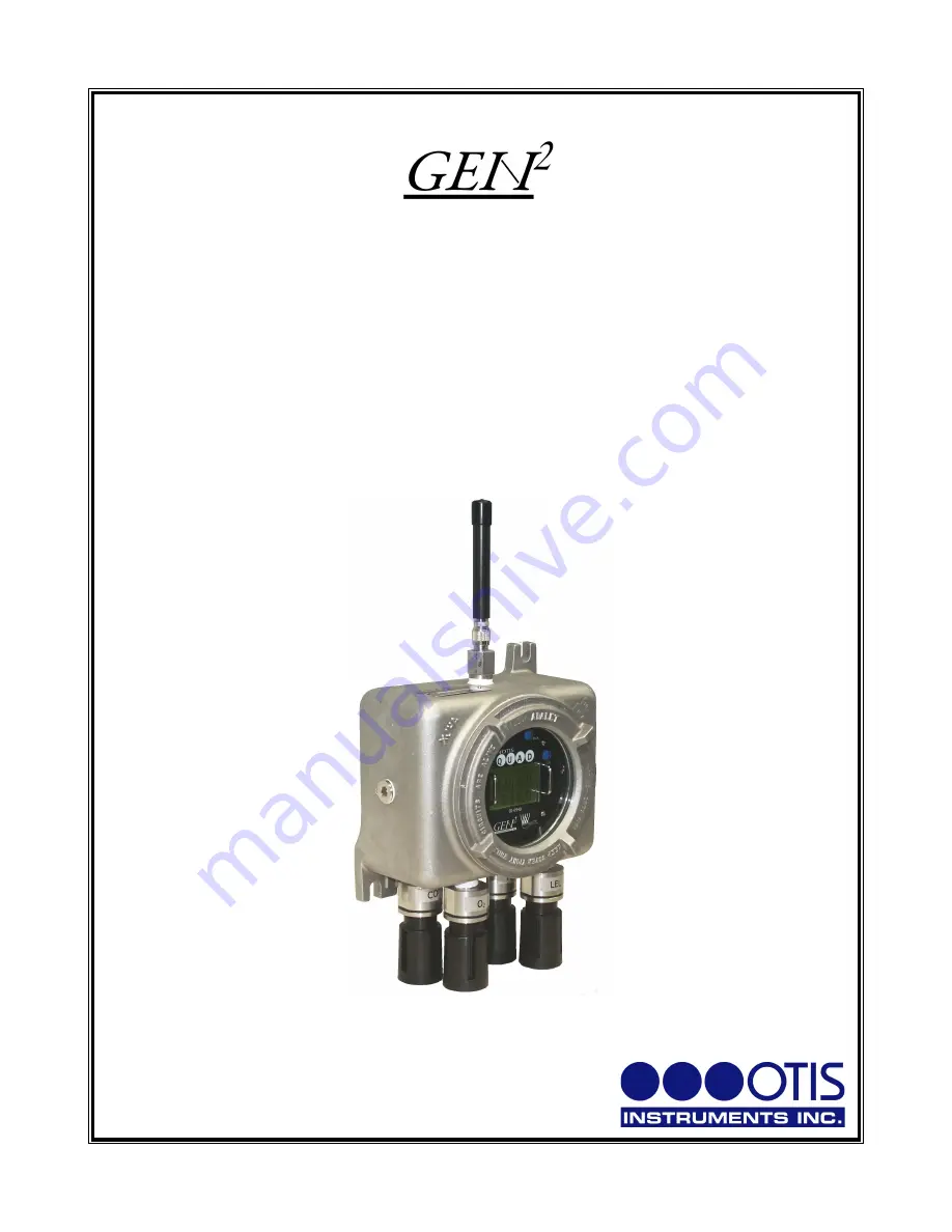
Model OI-6940 Notis Quad
4-Gas Sensor Assembly
__________________________________
Operation Manual
Revision 2.0w
________________________________________________________________________________
______________________________________________________
Page 1: ...4 Gas Sensor Assembly __________________________________ Operation Manual Revision 2 0w ________________________________________________________________________________ ______________________________...
Page 2: ...n and configuration With all adjustments made at the sensor assembly one man non intrusive calibration is quick easy and allows the sensor housing and enclosure to remain Class I Division 1 Group C an...
Page 3: ...5 Setting Contrast 16 Return to Factory Default Settings 17 Sensor Settings Menu Mode 19 Entering Sensor Settings 19 Sensor Settings Setup 20 Sensor On Off Setting 21 Sensor Null 22 Sensor Calibration...
Page 4: ...odel OI 6940 Notis Quad 4 Gas Sensor Assembly This document should be read before initial operation of the product Should a question arise during the use of the product this document will serve as a f...
Page 5: ...an Otis Instruments Inc distributed magnet However if the enclosure lid is removed for whatever reason the OI 6940 Notis Quad certification is not valid To avoid invalidating the certification once th...
Page 6: ...Complete System Diagram The following diagrams should be consulted for identification of the system and all parts that may be referred to in this Operation Manual Complete System External 6...
Page 7: ...Terminal Board Internal Diagram Battery Board Internal Diagram 7...
Page 8: ...revious screen touch MENU to select the displayed option or in cases when BACK is displayed on the top left side of the Display Screen to return to the previous option and touch BACK to return to the...
Page 9: ...are in the Advanced Menu Mode When in Normal Operating Mode the radio sends a transmission once per minute approx when no sensor is seeing gas When at least one sensor is seeing gas the radio sends a...
Page 10: ...s functions When powered on the device is fully functional and access to system and settings menus is allowed 1 Touch an Otis Instruments Inc distributed magnet to the ADD indicator label on the left...
Page 11: ...ormation From 29 to 15 the Display Screen will show the WireFree logo and unit information From 14 to 0 the Display Screen will show the Notis Quad logo and unit information 3 When the Notis Quad s Di...
Page 12: ...splay Fault 9 for that sensor channel 1 Touch and hold an Otis Instruments Inc distributed magnet against the right side of the Notis Quad for four seconds to activate SUB and turn off the device 2 Wh...
Page 13: ...touch SUB to return to the previous screen touch MENU to select the displayed option or in cases when BACK is displayed on the top left side of the Display Screen to return to the previous option and...
Page 14: ...ng illustration Setting Network ID 1 Touch the magnet to MENU to enter Global Settings Menu Mode The display screen should resemble the following illustration 3 Touch MENU SELECT to setup the Network...
Page 15: ...anipulate the Network I D Setting NOTE The Network I D may be set between 1 and 52 when using a 900 MHz or between 1 and 78 when using a 2 4 GHz radio 6 Once the desired Network I D Setting is display...
Page 16: ...o Screen the Display Screen should resemble the following illustration NOTE Touch ADD SUB to turn the backlight On Off while viewing the Info Screen 3 After the information has been viewed touch MENU...
Page 17: ...g NOTE The contrast may be set between 0 and 255 If ADD or SUB is continuously touched the number sequence will loop e g If ADD is touched when the Display Screen shows 255 the next number to appear w...
Page 18: ...O2 High set to 22 0 O2 Low set to 19 0 all other gases set to 4 of full scale Set to the value that the autocal will cal to O2 is 25 all other gases set to 50 of full scale Cal method set as manual e...
Page 19: ...Info Sensor Last Time Null Cal and Sensor Return Null Cal to Default When navigating through the Sensor Settings Menu Mode touch an Otis Instruments Inc distributed magnet to the corresponding indicat...
Page 20: ...DD NEXT to enter the Sensor Settings Menu Mode for Sensor 1 The Display Screen should resemble the following illustration 2 Touch MENU SELECT to enter Sensor 1 Settings Setup If no changes are needed...
Page 21: ...menu option 2 Touch ADD ON to turn Sensor 1 On Touch SUB OFF to turn Sensor 1 Off 3 Once the desired setting is displayed on the screen SENSOR1 On or SENSOR1 Off touch MENU BACK or BACK BACK 4 If the...
Page 22: ...perating Mode In the following illustration Sensor 1 is Off and Sensors 2 3 and 4 are On while in Normal Operating Mode Sensor Null 1 Touch ADD NEXT to continue to the next setting Sensor 1 Null 2 Tou...
Page 23: ...ection of the Operation Manual is for Sensor Setup only For Null and Calibration instructions see the Calibration section of this operation manual Radio Address Setting 1 Touch ADD NEXT to continue to...
Page 24: ...scrolling through the Radio Address Setting Options address settings that are already in use will not be available NOTE The Radio Address can be set between 1 and 255 NOTE Two sensors cannot have the...
Page 25: ...he Sensor 1 Relay Test setting in increments of 1 20th of the full sensor range until the value is high enough to trigger the pre set alarms NOTE The radio will only send the sensor that is in Relay T...
Page 26: ...will be a Background High and a Background Low to set When using any other sensor type there will only be one Background to set NOTE When using an O2 sensor the Background High is from 19 0 to 25 0 a...
Page 27: ...e next menu option 3 If MENU was touched the Display Screen should resemble one of the following illustrations 4 Touch ADD NEXT or SUB PREV to toggle between Manual or Auto as the Sensor 1 Calibration...
Page 28: ...Sensor 1 Info touch ADD NEXT to continue to the next menu option 3 If MENU was touched the Display Screen should resemble the following illustration NOTE Touch ADD SUB to turn the backlight On Off whi...
Page 29: ...reset since the last time the sensor was nulled caled the Display Screen will show NEVER NOTE The Last Time Since Null Cal is only calculated when the Notis Quad is turned On NOTE The Last TimeSince...
Page 30: ...ult touch ADD NEXT to continue to the next menu option 3 If MENU was touched the Display Screen should resemble the following illustration 4 Touch ADD YES to return Sensor 1 s Null Cal to default Touc...
Page 31: ...to the next screen 7 Select one of the following options Touch ADD NEXT to return to the Sensor Setup Menu Mode NOTE All sensors must be setup individually To setup the next sensor use this option tou...
Page 32: ...Each sensor must be nulled calibrated individually After all steps in this section are complete for Sensor 1 repeat the instructions for each consecutive sensor NOTE Do not cover the hole in the calib...
Page 33: ...creen should resemble the following illustration 3 Touch MENU SELECT to select the Sensor 1 Settings Menu NOTE To Null Sensor 2 3 or 4 touch ADD NEXT one two or three more times then touch MENU 4 Touc...
Page 34: ...he backlight will turn Off and the Display Screen will begin counting down from 12 to 0 as shown below If SUB NO is selected the Display Screen will return to the original Sensor 1 Null screen NOTE Wh...
Page 35: ...e displayed if the voltage is above 1 volt If the voltage is wrong when using a negative sensor F5 will be displayed if the voltage is less than 1 volt or higher than 2 4 volts Positive sensors are H2...
Page 36: ...he Sensor Setup Menu Mode section of this Operation Manual The following instructions are for Manual Calibration For Automatic Calibration instructions see the previous section of this Operation Manua...
Page 37: ...number on the Display Screen has stabilized or after approximately 90 seconds touch ADD increase or SUB decrease to manipulate the reading shown on the Display Screen until the displayed reading matc...
Page 38: ...nu Mode section of this Operation Manual The following instructions are for Automatic Calibration For Manual Calibration instructions see the next section of this Operation Manual 1 After the sensor h...
Page 39: ...ld resemble the following illustration 6 Touch ADD YES to calibrate the sensor or SUB NO to return to the Sensor 1 Cal screen 7 If ADD YES was touched the Display Screen should resemble the following...
Page 40: ...nguard from the sensor housing 11 Replace the rainguard of the sensor that is being calibrated with an Otis OI 410 Calibration Cup 12 Apply a known calibration gas to the OI 410 Calibration Cup that i...
Page 41: ...120 seconds HCl 310 seconds Cl2 and H2 180 seconds ClO2 360 seconds HCN 170 seconds F2 320 seconds HF 330 seconds 15 Once calibrated correctly the Display Screen will show the value that is currently...
Page 42: ...Sensor Calibration cont 16 Unscrew the OI 410 Calibration Cup 17 Reattach screw on the sensor rainguard to the sensor housing 42...
Page 43: ...e done in a non classified environment where no explosive gas is present The Notis Quad uses an Otis Lithium Ion 76AH battery pack with connector New batteries should only be obtained from Otis Instru...
Page 44: ...the standing eyelets NOTE Do not use any metal object to help remove the Front Panel NOTE Do not remove any connecting wires 4 Gently lay the Front Panel to the side of the Notis Quad so that the batt...
Page 45: ...Battery Mount Strip back onto the Battery Board 10 Replace the Front Panel back in the enclosure by matching each mounting post to its corresponding eyelet inside the enclosure 11 Place the enclosure...
Page 46: ...rous level Failed alarm tests could be an indicator of the Notis Quad needing a sensor s replaced 1 Power off the device by touching and holding an Otis Instruments Inc distributed magnet against the...
Page 47: ...Do not use any metal object to remove the sensor NOTE Be careful to not remove the sensor board when removing the sensor 5 Slide the new sensor into device matching the sensor prongs to the correspon...
Page 48: ...rrent antenna can be replaced by an Otis Instruments Inc approved 2 4 GHz or 900 MHz antenna 1 Power off the device by touching and holding an Otis Instruments Inc distributed magnet against the SUB i...
Page 49: ...Antenna Replacement cont 3 Unscrew the current Antenna Connector from the Antenna Fitting 4 Screw the new Antenna onto the Antenna Fitting 5 Power on the device by touching the magnet to ADD 49...
Page 50: ...e displayed if the voltage is outside the voltage range of working 2 If the Notis Quad cannot communicate with the sensor Solution Check the voltage of the sensor Replace the sensor if still in Fault...
Page 51: ...lay Graphical LCD sunlight readable transflective LED back light 160x104 pixel resolution Interface Four push buttons MENU BACK ADD SUB four corresponding magnetic non intrusive switches non intrusive...
Page 52: ...the manufacturer In the event that a product should fail to perform up to manufacturer specifications during the applicable warranty period contact the product s authorized reseller or return the pro...
Page 53: ...Otis Instruments Inc Corporate Office 2200 E Villa Maria Dr Bryan TX 77802 979 776 7700 www otisinstruments com 53...