background image

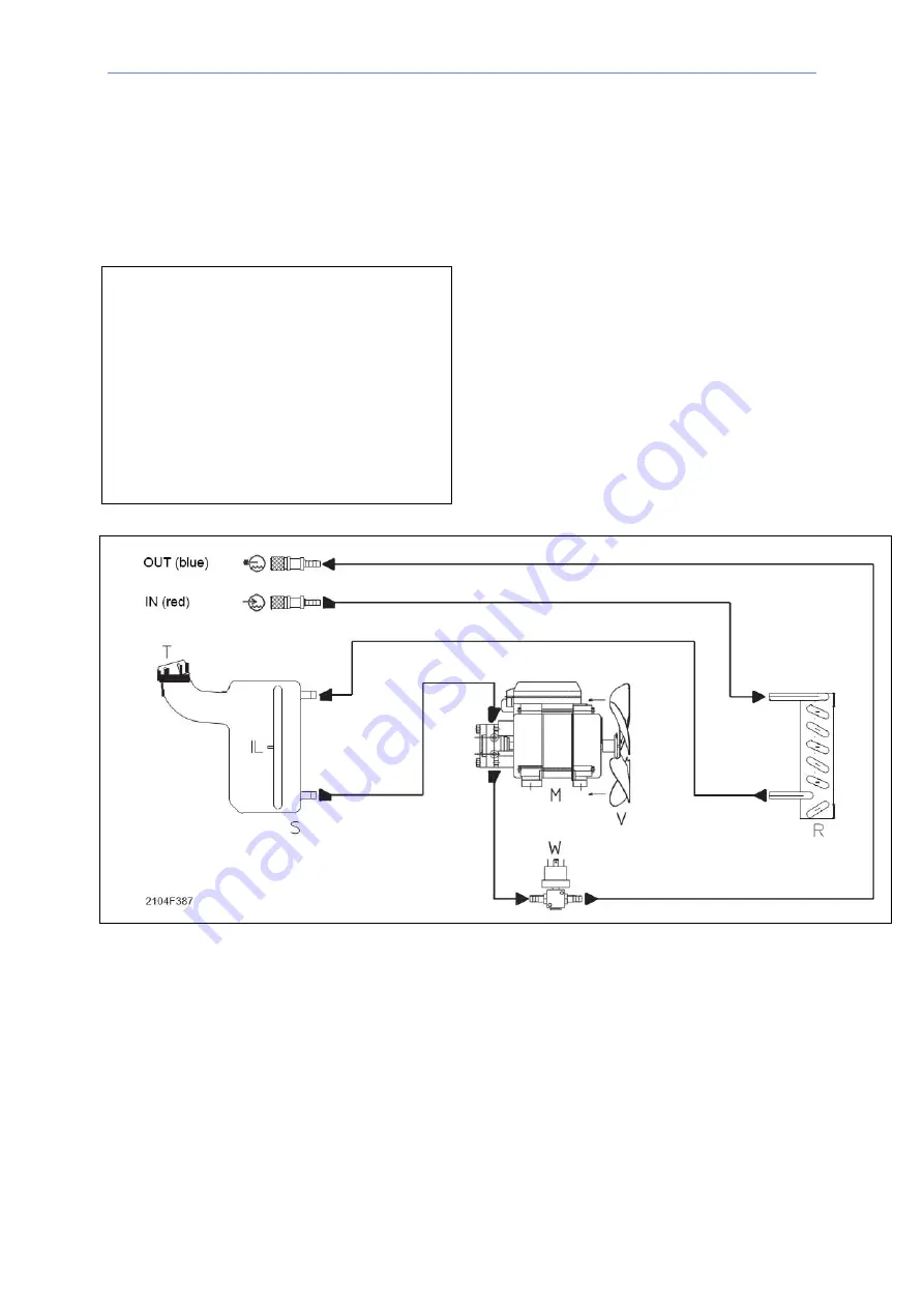
Hydraulic diagram


16 

HR-22-23 (EN) 


14  Hydraulic diagram  


14.1  Key to the electrical diagram 


• IL Depth gauge 

• IN Torch outlet (red) 

• M Electric pump  

• OUT Torch intake (blue) 

• R Radiator 

• S Tank  

• T Tank cap with micro valve 

• V Fan  

• W Pressure switch 


Summary of Contents for HR 22

Page 1: ...HR 22 23 User Manual...

Page 2: ...ures 7 4 Description 8 5 Technical Data 8 6 Usage Limits IEC 60974 1 9 7 Installation 9 8 Outer view of the HR 22 23 10 9 Electrical wiring of the welding cooling unit and successive mechanical coupli...

Page 3: ...all persons who operate with the device have red and understood the operating instructions in this manual If you don t have sufficient knowledge and experience concerning the operation and the safe u...

Page 4: ...plug must be checked and any damage eliminated The electrical equipment must be tested at regular intervals Use cables of sufficient diameter The ground cable must be fastened as close as possible to...

Page 5: ...ave to wear earmuffs When you manually remove the hot metal slag wearing safety glasses with side flaps is required Present persons have to keep their distance The entire welding area must be secured...

Page 6: ...use respirators and additional air supply In small rooms in boilers in the ditch etc the welders have to be backed up by another person Provided that all requirements are met to prevent accidents Weld...

Page 7: ...s and cause a short circuit During welding some parts of the machine exceeds 100 C Therefore these parts are protected with a thermostat Whenever you will notice any overheating you have to turn off t...

Page 8: ...tegral part of the welder 5 Technical Data Table1 Model HR22 HR23 Single phase input V 1 230 20 3 400 20 Frequency Hz 50 60 50 60 Max power supply kW 0 3 0 3 Max current absorbed A 1 35 0 9 Delayed fu...

Page 9: ...est that you should avoid installing the system close to Signalling control and telephone cables Radio and television transmitters and receivers Computers and control and measurement instruments Secur...

Page 10: ...connector for water intake Blue snap in connector for water outlet Cap with micro valve for filling the tank with coolant Cable for electric connection of the cooling unit to the welding power source...

Page 11: ...ructions attached and contained in the accessories packet Prior to beginning the operator has to assure that close at hand there is both the welding power source example DTX 2200 AC DC and the cooling...

Page 12: ...packet A Unscrew the tank s cap and using a funnel fill it with distilled water In case of particularly rigid climates with air temperature near to 0 C it is necessary to add antifreeze to the coolin...

Page 13: ...Make sure all joints are tight and that there are no leaks Periodically clean the radiator with compressed air to eliminate the dust that reduces the cooling capacity IMPORTANT Original spare parts h...

Page 14: ...GRAPHIC SYMBOLS ON THE MACHINE Fuse Cold water outlet Hot water intake for cooling in the unit Grounding Warning Before using the equipment you should carefully read the instructions included in this...

Page 15: ...iagram 15 HR 22 23 EN 13 WIRING DIAGRAM 13 1 Key to the electrical diagram 13 2 Colour key Bl Blue Gg Grey GV Yellow Green Mr Brown Nr Black CA Power supply connector F Fuse M Electric pump W Pressure...

Page 16: ...m 16 HR 22 23 EN 14 Hydraulic diagram 14 1 Key to the electrical diagram IL Depth gauge IN Torch outlet red M Electric pump OUT Torch intake blue R Radiator S Tank T Tank cap with micro valve V Fan W...

Page 17: ...3783 403783 Terminal for 3x2 poles male connector 4 403779 403779 3x2 Poles male connector 5 413535 413535 Auxiliary wiring 6 446631A 420926B Right panel 7 451740 451740 Fuse holder 8 428879 429049 Fu...

Page 18: ...14 460253 460253 Tank 15 457761 457761 Water distributing frame 16 453246 453246 Pressure switch 17 486564 486564 Fan 18 418846 418846 Capacitor 19 465464 465464 Electropump support 20 345460 345461 E...

Page 19: ...To ask for spare parts clearly state 1 The code number of the piece 2 The type of device 3 The voltage and frequency read on the rating plate 4 The serial number of the same EXAMPLE 2 Pieces Article n...

Page 20: ...OTC DAIHEN EUROPE GmbH Krefelder Strasse 675 677 D 41066 M nchengladbach Germany Phone 49 0 2161 694970 Fax 49 0 2161 6949761...

Reviews: