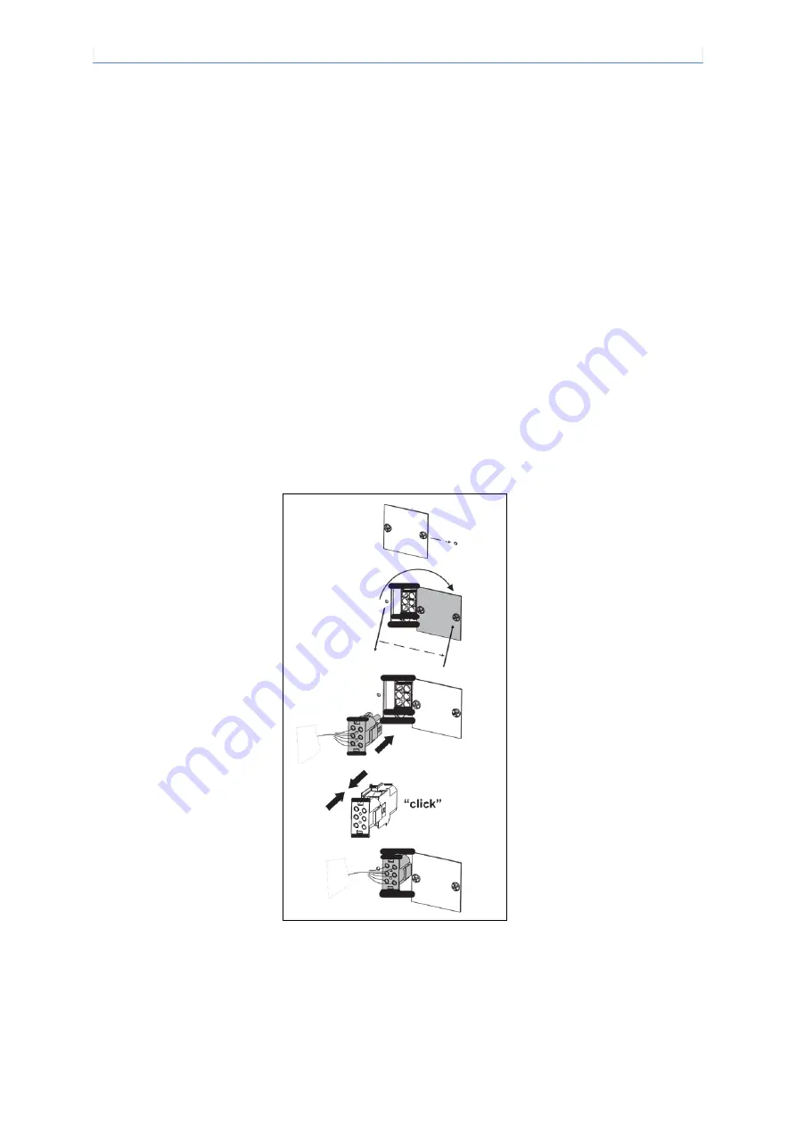
Electrical wiring of the welding cooling unit and successive mechanical coupling
11
HR-22-23 (EN)
9 Electrical wiring of the welding cooling unit and
successive mechanical coupling
The cooling unit cannot function in an autonomous manner, therefore it must be connected electrically, in order to
operate, to the welding power source, making the coupling between the 3x2 pole male connector in the cooling
devise (Pos. 4, Image 1) and the corresponding female on the welding power source (to ignite the female
connector just remove its specific covering (Image 2) located under the base of the machine) following the
assembly instructions attached and contained in the accessories packet.
Prior to beginning, the operator has to assure that close at hand there is both the welding power source
(example: DTX-2200 AC/DC) and the cooling device (example: HR 22) and that both are working at the same
feed voltage (see the two data panels positioned under the respective bases).
Upon final connection, even the pressure switch will be connected. The pressure switch has a protective function.
It does not allow the welding power source to emit voltage in case the water pressure and therefore the cooling
capacity, is inferior to the calibration value.
Having terminated the electrical connections, complete the mechanical coupling by means of screws and
fastening clamps following the assembly instructions attached and contained in the accessories packet.
Image 2
Summary of Contents for HR 22
Page 1: ...HR 22 23 User Manual...


