background image

20

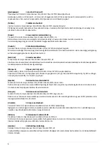
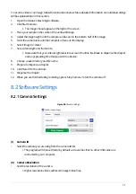
1.  First

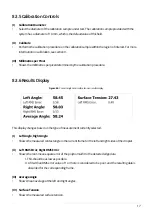
I. Displays the first frame in the video.

2. 

Previous

I. Displays the previous frame in the video.

3. 

Play (visible while paused)

I. Cycles through every frame in the video.
II. If ‘Analyse’ button is checked, the contact angle will be measured for each frame.

4. 

Pause (visible while playing)

I. If pressed after ‘Play’, the video will stop at the current frame.

5. 

Next

I. Displays the next frame in the video.

6. 

Last

I. Displays the last frame in the video.

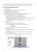
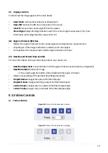
(II) Frame

• 

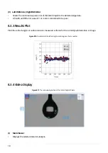
Displays the index number of the frame being displayed.

• 

The first frame in the video has an index of 0.

8.3.10 Data Saving

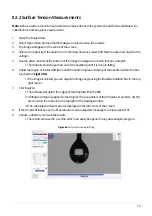
Results files are saved in a tabular format as .csv files, which can be opened with most spreadsheet 
programs. The file contains seven columns of measurement results, which are described in the 

Table 8.1. 

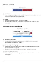
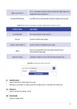
The save directory and file name can be selected using the controls shown in 

Figure 8.14.

Table 8.1. 

Column names and descriptions for contact angle data saved in the results .csv file.

Column Name

Description

Frame Number

The frame number in the video file

Time (s)

The time at the frame number

Left Angle (°)

Left fitted contact angle

Right Angle (°)

Right fitted contact angle

Average Angle (°)

Mean average of the right and left angles

Left Contact Point

The x coordinate (in pixels) at the point where the left edge of the 
droplet intercepts the baseline

Summary of Contents for L2004A1

Page 1: ...USERMANUAL Manual Version 1 1 D Product Code L2004A1 Product Version 1 1 Software Version 3 0 CONTACT ANGLE GONIOMETER ...

Page 2: ...ion 10 8 Operation 10 8 1RecordingaVideo 10 8 2SoftwareSettings 11 8 3PerformingMeasurements 13 9 Calibration 22 9 1CalibrationRecording 22 9 2CalibrationAnalysis 22 10 AdvancedMeasurementGuide 22 10 1RegionofInterest ROI 22 10 2PolynomialFitting 23 10 3CannyEdgeDetection 24 10 4PendantDropFitting 26 11 Troubleshooting 28 12 Relatedproducts 29 12 1RelatedConsumables 29 12 2RelatedEquipment 29 ...

Page 3: ...thPCsoftwarethatprovidesasimpleandintuitiveinterfacefor contactanglemeasurements TheOssilaSolarCellPrototypingPlatformisacomplementarycollectionofsubstrates materials and equipmentaspartofahigh performancestandardphotovoltaicreferencearchitecture Thisplatform enablesresearcherstoproducehigh quality fully functionalsolarcellswhichcanbeusedasareliable baseline Formoreinformation ossila com pages sol...

Page 4: ...ethattheDoCisissuedunderoursoleresponsibility andbelongstothefollowingproduct Product L2004A1ContactAngleGoniometer Serialnumber L2004A 0105 1000 3000 xxxx Objectofdeclaration L2004A1 ContactAngleGoniometer Theobjectofdeclarationdescribedaboveisinconformity withtherelevantUnionharmonisationlegislation EMCDirective2014 30 EU RoHSDirective2011 65 EU Signed Name DrJamesKingsley Place Sheffield Date 0...

Page 5: ...τότηταςΕΕ Κατασκευαστής OssilaLtd SolproBusinessPark WindsorStreet S47WD ΗνωμένοΒασίλειο ΔηλώνουμευπεύθυναόnοαναφερόμενοςεξοπλισμόςσυμμορφώνεταιμετησχεnκήνομοθεσίαεναρμόνισηςτηςΕΕπουυπάρχει σnςπροηγούμενεςσελίδεςτουπαρόντοςεγγράφου Español DeclaracióndeconformidadUE Fabricante OssilaLtd SolproBusinessPark WindsorStreet S47WD ReinoUnido Declaramosbajonuestraúnicaresponsabilidadqueelsiguienteproduct...

Page 6: ...dsorStreet S47WD ReinoUnido Declarasobsuaexclusivaresponsabilidadequeoequipamentoindicadoestáemconformidadecomalegislaçãodeharmonização relevantedaUEmencionadana s página s anterior es destedocumento Română DeclaraţiedeconformitateUE Producător OssilaLtd SolproBusinessPark WindsorStreet S47WD RegatulUnit DeclarăpeproprierăspunderecăechipamentulprezentatesteînconformitatecuprevederilelegislaţieiUEd...

Page 7: ...fromothers Takecaretoavoidtrappingfingerswhileadjustingthetiltstageposition Table4 1 ContactAngleGoniometerandContactAnglesoftwarerequirements Table4 1detailsthepowerrequirementsforthesystem andtheminimumcomputerspecificationsforthe OssilaContactAnglesoftware Power 12V 1ADC suppliedwiththesystem OperatingSystems WindowsVista 7 8 or10 CPU DualCore2GHz RAM 2GB AvailableHardDriveSpace 250MB MonitorRe...

Page 8: ...ntedcopyoftheusermanual 25µlsyringewithbluntneedle Syringeclampingmechanism Examinethecomponentsforevidenceofshippingdamage Ifdamagehasoccurred pleasecontact Ossiladirectlyforfurtheraction Theshippingpackagingwillcomewithashockindicatortoshowif therehasbeenanymishandlingofthepackageduringtransportation TheContactAngleGoniometermeasurementspecificationsareshowninTable6 1 andthephysical specificatio...

Page 9: ... Alternatively thesoftwarecanbedownloadedfrom ossila com pages software drivers Videorecordingisperformedinthe Capture Tablocatedinthetopleftofthesoftware 7 Installation 8 Operation Table6 2 ContactAngleGoniometerphysicalspecifications Figure8 1 SoftwareTabs CaptureandAnalyse StageDimensions 50mmx50mm MaximumDropletWidth 20mm OverallProductDimensions Width 95mm Height 170mm Depth 320mm MaximumSamp...

Page 10: ...display 6 Select Image or Video 7 Setavideolengthandframerate I Makesurethatyourvideolengthtakesintoaccountthetimeitwilltaketodispensethedroplet andanyspreadingtimethatyouwishtoobserve 8 Chooseasavedirectoryandfilename 9 Preparetodispenseadroplet 10 Click Record inthecontrols 11 Dispensethedroplet 12 Whenyouarefinishedtakingrecordings press StopCamera toturnthecameraoff 8 2 1CameraSettings I Camer...

Page 11: ...tallengthoftimetorecordforinseconds I Chooseanumberbetween0 1and3600 1hour II Thedefaultis10seconds II FrameRate Setstheframerateinframespersecond I Thiswillupdatetheincrementtomatchthechosenframerate II Defaultis20framespersecond III TimeIncrement Setsthetimeincrementinseconds I Thiswillupdatetheframeratetomatchthechosenincrement II Defaultis0 05seconds 8 2 2RecordingSettings Figure8 3 RecordingS...

Page 12: ...rwritten II Videofilesaresavedas avifiles Imagefilesaresavedas pngfiles VI AnalyseRecordedImage Video Ifthisboxischecked thesoftwarewillloadtherecordedfileintotheanalysistabafterithasfinished recording VII RecordButton Startsvideorecording I Thiswillsaveasetnumberofframesdeterminedbythechosenvideolengthandthe framerate 8 3PerformingMeasurements Bothcontactangleandsurfacetensionmeasurementsareperfo...

Page 13: ...geisslanted orthestagewasnotcompletelylevel youcanadjustthebaselineangle usingthe BaselineRotation controlinthetoprightcorner IV Youcanalsomakefineadjustmentstothebaselineheightusingtheupanddownarrowsin thetoprightcorner 7 Click Analyse I ThesoftwarewilldetecttheedgesofthedropletwithintheROI II Afittingtechniqueisappliedtothedroplet dependingonitsestimatedangle 10 CircleFit 10 PolynomialFit III Th...

Page 14: ...gleusingthe BaselineRotation boxinthetop rightcorner 7 Click Analyse I ThesoftwarewilldetecttheedgesofthedropletwithintheROI II Afittingtechniqueisappliedtothedroplet Theparametersofthefit radius Bnumber X0 Y0 areshowninthecontrolstothetoprightoftheviewingwindow III Thecalculatedsurfacetensionisdisplayedintheleftcornerofthescreen 8 Ifthedropletfitlookspoor thefitparameterscanbeadjustedmanuallytoac...

Page 15: ...alculatedcontactanglesaredisplayedinthe resultsdisplay I ContactAngle PendantDrop Choosebetweenthetwopossiblemeasurementtypes Thiswillaffectwhichmeasurementis performedwhenthe Analysis buttonispressed II DropDensity PendantDropOnly Selectthedropdensityoftheliquidunderinvestigation Thisdensityisusedalongwiththedroplet fittingtodeterminethesurfacetension Ifasuitabledensityisnotinthelist select AddNe...

Page 16: ...determinedbythecalibrationprocedure Thisdisplaychangesbasedonthetypeofmeasurementcurrentlyselected I LeftAngle RightAngle Showsthemeasuredcontactangleinthecurrentframefortheleftandrightsidesofthedroplet II LeftRMSError RightRMSError Showstheroot mean squareerrorofthepolynomialfittothedetectededgedata I Thisshouldbeaslowaspossible II AfitwithanRMSerrorvalueof1ormoreisconsideredtobepoor andtheresult...

Page 17: ...of1ormoreisconsideredtobepoor 8 3 3ResultsPlot 8 3 4VideoDisplay Plotsthecontactanglesorsurfacetensionsmeasuredvsframeforthecurrentlyselectedvideoorimage Figure8 10 Resultsplotoftheleftandrightcontactanglesvsframenumber Figure8 11 ThemainviewingsectionoftheContactAnglesoftware I MainViewer Displaystheselectedvideoforanalysis ...

Page 18: ...easurementisdefinedbythebottomofthebox IV BaselineandPedantDropControls Formoreinformationonthependantdropcontrols seesection10 4 BaselineAdjustmentmovesthebottomoftheregionofinterestupanddownbyasinglepixel BaselineRotationrotatestheimage I Thisisusedtoalignthebottomofthedropletwiththeregionofinterest Allowsmanualeditingofthependantdropfittingparameters DropletRadiuschangestheradiusofthefitteddrop...

Page 19: ...ohasanindexof0 8 3 10DataSaving Resultsfilesaresavedinatabularformatas csvfiles whichcanbeopenedwithmostspreadsheet programs Thefilecontainssevencolumnsofmeasurementresults whicharedescribedintheTable8 1 ThesavedirectoryandfilenamecanbeselectedusingthecontrolsshowninFigure8 14 Table8 1 Columnnamesanddescriptionsforcontactangledatasavedintheresults csvfile ColumnName Description FrameNumber Thefram...

Page 20: ...ofthesimulatedpendantdropto thedetecteddropletedge DropVolume µL Calculateddropletvolumeofthesimulatedpendantdrop RightContactPoint Thexcoordinate inpixels atthepointwheretherightedgeofthe dropletinterceptsthebaseline DropletWidth Pixels Thedifferenceinpixelsbetweentheleftandrightcontactpoints I SaveDirectory Setsthedirectoryinwhichvideosaresaved Directorycanbeinputmanuallyorselectedusingthebutton...

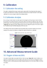
Page 21: ...ndsmostofthesphere asshown inFigure9 1 Click Calibrate andthesoftwarewillfitacircletotheedgeofthesphere Thisisseenasagreen line The MillimetresperPixel fieldwillupdatewiththenewvalue Thesoftwarewillsavethenewcalibrationvalueanditwillremainevenwhenthesoftwareisclosedand reopened Ifthecamerafocaldistanceischanged thesystemwillneedtobere calibrated Figure9 1 Calibratingthesoftwareusingacalibrationsph...

Page 22: ...geabovethebaselinewillbeusedinthefittingandresultantcontactanglecalculations Thetop leftandrightsidesoftheROIboxareusedtoexcludeanyunwantedfeaturesfromtheimage If thereisaseconddropletinthesameimage thisshouldbeexcludedfromtheregionofinterest 10 2PolynomialFitting Ifthecontactangleisabove10 thenthesoftwarewillfitapolynomialtotheedgeofthedroplet The polynomialfitisoverlaidontheimageasagreenline The...

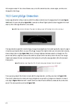
Page 23: ...tnessbetweenpixelsinastraightline The pixelonthelefthasalightnessvalueof50 whichincreasesto240overthe6pixelsintheline Thechange inlightnessbetweenthetwocentralpixelsisthehighest shownbythesteepgradientofthelinebetween thesepoints 10 3CannyEdgeDetection Figure10 4 Lightnessvaluechangefrom50to240 withasteepgradientbetweenthecentraltwopixels Therearetwogradientthresholdsinvolvedwiththeedgedetection a...

Page 24: ...illalsobecountedasanedge ThisisdemonstratedinFigure10 6 wherethegradientchangeinthebottomrowofpixelsdoesnotpass threshold1butdoespassthreshold2 Asitisadjacenttothetoprowwhichdoespassthreshold1 itisstill countedasanedge Rowsadjacenttothisrowthatpassthreshold2willalsobecountedasedges pointbin Figure10 5 Figure10 7 Cannyedgedetectionthresholdcontrols Defaultsthresholdsaresetto200and100 Ifarowfallsbel...

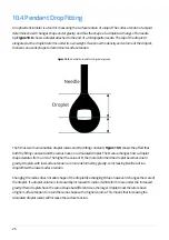
Page 25: ...t Ifadropletvolumeisincreasedbyincreaseditsradius itwilldeformmoreundertheincreased gravity Iftwodropletshavethesameshapebutdifferentsizes thelargerdropletmustthereforehave ahighersurfacetensiontoretainthesameshapewithahighervolume Thismeansthatincreasingthe simulateddropletradiuswillincreasethesurfacetension 10 4PendantDropFitting Anopticaltensiometerisatoolformeasuringthesurfacetensionofaliquid ...

Page 26: ...ts Itthen comparesthesimulateddropletswiththedetectededgeofthedropletintheregionofinterest The simulatedfitthatmostcloselymatchesthedetectededgeischosenasthe real droplet Thedifference betweenthesimulatededgeandthedetectededgeistherootmeansquarederror RMSE Thisisdisplayed whenameasurementisperformedandcanbeusedasanindicatorofhowcloselythesimulateddroplet matchedthedetectededge ...

Page 27: ...ply andthattheplugisconnectedtoboththe adaptorandaworkingpowersocket b ContactOssilaforareplacementpower supplyadaptor Softwaredoes notstart a ThewrongversionofWindowsisinstalledon thecomputer b Thesoftwarehasnotinstalledproperly a InstallthesoftwareonacomputerwithWindows Vistaornewer b Tryreinstallingthesoftware Cannotdetectthe camera a TheUSBcablemaynotbe connectedproperly b TheUSBcablemaynotbec...

Page 28: ...ance specs and simple to use intergrated software at a reasonable cost Our range of 15 x 20 mm ITO substrates for OPV OLED and sensing applications These substrates are coated with a 20nm layer of synthetic quartz Produce high quality coatings without any substrate warping Perfect for busy labs with limited space Product codes C121 Product code C2001V1 Product codes L2005A1 Product code L2006A1 Pr...

Page 29: ......

Reviews: