OSEE BCM-170 Series User Manual Download Page 20


Americas, Ltd.


BCM-170 Series LCD Monitor


User Manual


16 


Ÿ


Dash of select items is the default value. 

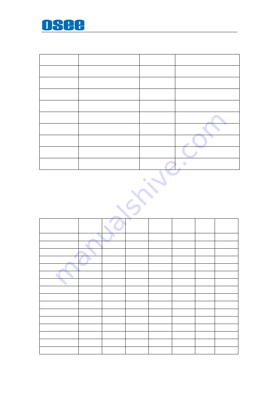
Table 5.1.2. GPI Control 

MONO 

Low: MONO; 
High: NORMAL 

BLUE ONLY 

Low: BLUE ONLY; 
High: NORMAL 

ASPECT 

Low: 16:9 
High: 4:3 

NATIVE 

Low:  NATIVE(In  center);  High: 
NORMAL 

AREA MARKER 

Low: Enabled; 
High: Disabled 

SDI1 

Switch at the falling edge, when 
switching to the other input, exit. 

CENTER 
MARKER 

Low: Enabled; 
High: Disabled 

SDI2 

Switch at the falling edge, when 
switching to the other input, exit. 

SAFETY 
MARKER 

Low: Enabled; 
High: Disabled 

VIDEO1 

Switch at the falling edge, when 
switching to the other input, exit. 

OVER SCAN 

Low: OVER; 
High: NORMAL 

VIDEO2 

Switch at the falling edge, when 
switching to the other input, exit. 

UNDER SCAN 

Low: UNDER; 
High: NORMAL 

HDMI 

Switch at the falling edge, when 
switching to the other input, exit. 

H DELAY 

Low: H DELAY; 
High: NORMAL 

TALLY GREEN 

Low: ON; 
High: OFF 

V DELAY 

Low: V DELAY; 
High: NORMAL 

TALLY RED 

Low: ON; 
High: OFF 

H/V DELAY 

Low: H/V DELAY; 
High: NORMAL 

Note: GPI control: when itchanges it would be as a control value of response control. If the 

level does not change, but there are other control caused by changes in the control value, 

perform this change. When boot, detect the GPI input status after initialization. If a GPI 

value is low, the monitor will control the corresponding operation. The TALLY is directly 

control by the level. 


Table 5.1.3 Function 

Function 

Composit

e & Y/C 

YPbPr(S

D) 

YPbPr(H

D) 

SDI(SD) 

SDI(HD) 

HDMI(

SD) 

HDMI(HD

Volume(S) 

Contrast(S) 

Brightness(S) 

Chroma(S) 

Phase(S) 

O(NSTC) 

Aperature(S) 

Backlight(G) 

Color Temp(G) 

NTSC Setup(G) 

O(NSTC) 

Scan(S) 

Native(S) 

Aapect(S) 

Marker(G) 

Blue Only(G) 

Mono(G) 

H/V Delay(G) 

Summary of Contents for BCM-170 Series

Page 1: ...BCM 170 Series LCD Monitor U S E R M A N U A L l BCM 170 3HSV l BCM 170 HSV l BCM 170 SV l BCM 170 V...

Page 2: ...LCD Monitor Version V010000 Modified Decermber 13th 2012 COMPANY NAME OSEE Americas Ltd CONTACT US OSEE AMERICAS LTD 43218 CHRISTY STREET FREMONT CA 945638 Toll Free 866 625 6106 Tel 510 996 4499 Fax...

Page 3: ...70 HD l BCM 170 SD l BCM 170 A The images of BCM 170 HD monitor are adopted in the following descriptions Any of the different specifications between the device types are elaborated Before reading the...

Page 4: ...status 6 4 2 Supported Signal Format 7 4 3 Interface of rear panel 8 4 4 Interface of front panel 9 Chapter 5 Menu Description 10 5 1 Main menu 10 5 2 Status Display 17 5 3 Function Display 17 5 4 Ad...

Page 5: ...t brightness and contrast ratio By adopting the advanced 10 bit digital signal processing technology plus 3D comb filter de interlacing capability and accurate scaling ensures the BCM 170 Series LCD M...

Page 6: ...toves or other apparatus including amplifiers that product heat 5 A nameplate indicating operating voltage etc is located on the rear panel Install only in accordance with the instructions in the sect...

Page 7: ...ce Chapter 3 Product Introduction Unpackaging and installation Opening the box please check whether the device has been damaged during transport Check all the things listed on the packing list are rec...

Page 8: ...r cord with fastening 1 Note The packing list would be different according to the device type Please confirm the device type And the BCM 170 Series Monitor supports two modes of riding position The mo...

Page 9: ...Americas Ltd BCM 170 Series LCD Monitor User Manual 5 Rear panel Unit mm As the following figure Side view Unit mm As the following figure...

Page 10: ...and if the monitor doesn t support the input signal the display information will be UNKNOWN For the current input signal it will lock displaying the corresponding video format 2 the main screen status...

Page 11: ...r of the screen 9 MUTE The mute logo icon is It can be setup in the function key menu 4 2 Supported Signal Format l Support two channel analog video input with loop through output loop through output...

Page 12: ...ote O is the Supported signal format 4 3 Interface of rear panel Note The specs are subject to change without prior notice 1 video interface 3G HD SD SDI signal input output BNC x4 IN OUT Composite si...

Page 13: ...bPr and HDMI The machine retains input selection state Unused inputs can choose to skip through the menu F1 F5 function keys the function can be set via the FUNCTION menu Open the FUNCTION menu after...

Page 14: ...Americas Ltd BCM 170 Series LCD Monitor User Manual 10 Chapter 5 Menu Description 5 1 Main menu It displays as following fig 5 1 1 by pressing the MENU button Fig 5 1 1 Fig5 1 2 1 2 3...

Page 15: ...on within 60s the menu will automatically disappear 3 The main menu displays in the upper left corner of the screen with the translucent blue background and white font 4 The background of selected men...

Page 16: ...NDEF this item is disabled AUDIO METER G OFF ON MTER SELECT G CH1 2 G1 G2 G3 G4 G1 2 G1 3 G1 4 G2 3 G2 4 G3 4 G1 4 METER DIS MODE SIMPLE INTACT METER POSITION TOP BOTTOM when the METER DIRECTION is HO...

Page 17: ...1 TEXT2 TEXT3 TEXT4 in Y C NTSC signal SDI CC LOG OFF ON CONFIG I P MODE 1 S NORMAL FILM FIELD Note If the input is DVI signal it can be set but does not enable When it is set to 0 OVER LIMIT does not...

Page 18: ...ule COLOR SPACE OFF EBU SMPTE C ITU 709 FUNCTION KEY F1 SCAN NATIVE When the LCD resolution is less than the input image resolution continuously press NATIVE the display position will loop Or press SC...

Page 19: ...UP or DOWN button to select a character Press the ENTER key to select the next character and press the MENU key to exit edit BAUD RATE 2400 4800 9600 19200 38400 57600 115200 Note TSL V3 1 and TSL V4...

Page 20: ...AY High NORMAL TALLY GREEN Low ON High OFF V DELAY Low V DELAY High NORMAL TALLY RED Low ON High OFF H V DELAY Low H V DELAY High NORMAL Note GPI control when itchanges it would be as a control value...

Page 21: ...MENU it will display the status information as following If there is no operation for 10 seconds the menu would disappear INPUT SDI1 or others FORMAT 1080I50 DVI 1024X768 60 etc COLOR TEMP D65 SCAN M...

Page 22: ...VOLUME BRIGHTNESS CONTRAST CHROMA menu items If there is no operation for 10 seconds the menu would disappear 5 5 Source menu Source menu displays in the upper right corner of the screen with blue ba...

Page 23: ...DI1 X O O O O O O O SDI2 O X O O O O O O VIDEO1 O O X X X O O X VIDEO2 O O X X X O O X YC O O X X X O O X YPBPR O O O O O X O X HDMI O O O O O O X X Table 5 6 2 PBP screen size Ratio Signal 4 3 16 9 S...

Page 24: ...Specification 6 1 Description for Specification LCD Dimension 17 3 Screen Scale 16 9 Resolution 1920 H x 1080 V Color Depth 16 7M 24 bit Viewing Angle 178 H V Brightness 250 cd m 2 Contrast Ratio 1000...

Page 25: ...87 1366X768 1024X768 60 601 709 576I50 684X548 1366X768 1024X768 720X576 720X576 720X576 1366X768 1024X768 50 601 480P60 684X462 1366X768 1024X768 720X487 720X487 720X487 1366X768 1024X768 60 601 709...

Page 26: ...68 60 75 SXGA 1280x1024 1366X768 60 75 UXGA 1600x1200 1366X768 60 WXGA 1360X768 1360X768 60 WUXGA 1920x1200 1366X768 60 Don t display all OSD except FORMAT when SCAN is NATIVE Don t display MARKER whe...

Reviews: