background image

SecureSync 2400 Option Card Field Installation Guide

May 4, 2021

Page

1

©

O

ro

lia

20

19

 •

or

ol

ia

.co

m

Document Part Number 2400-5000-0052 Rev 2

Purpose of this Document

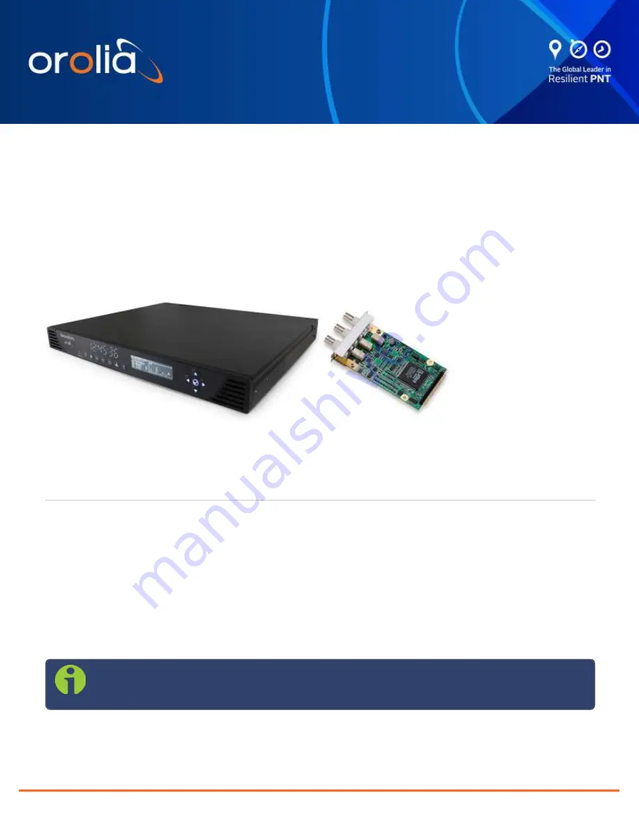
The SecureSync 2400 time and frequency synchronization system offers customizability and expandability via

the addition of a range of modular option cards. Depending on your unit's specifications, up to 6 cards can be

accommodated to offer not only synchronization to a variety of input references, but also numerous types of out-

put signals, supporting an extensive number of traditional and contemporary timing protocols.
Typically, SecureSync units are shipped with custom-ordered option cards pre-installed at the factory. In the

event that an option card is purchased at a later time, field installation will be necessary. This option card install-

ation guide contains information and instructions for installing option module cards in your SecureSync unit.
This procedure should only be attempted by qualified personnel, while following the enclosed safety instructions.

Note:

The installation procedure varies, depending on the type of option card and the installation

location to be installed. Read instructions completely before beginning.

Option Card Field Installation Guide

SecureSync 2400

Technical Note

Summary of Contents for SecureSync 2400

Page 1: ...nal and contemporary timing protocols Typically SecureSync units are shipped with custom ordered option cards pre installed at the factory In the event that an option card is purchased at a later time...

Page 2: ...equired and plug card into the slot 5 Connect any required cables and secure option card into place 6 Replace chassis cover power on unit 7 Log in to the SecureSync web interface verify the installed...

Page 3: ...hex M F Zinc pl brass 1 HM50R 03R5 0012 Cable tie 2 MP00000 In addition to the parts supplied with your option card ancillary kit you will need a 1 Phillips head screwdriver and may need a cable tie...

Page 4: ...mation window that displays 4 Save the configuration file to a directory where it will be safe Note The Reference Priority configuration must be saved BEFORE beginning with the hardware installation A...

Page 5: ...igits of the part number of your option card see label on bag b Inspect the back of the SecureSync housing and select an empty slot for the new card If the card is to be installed in one of the upper...

Page 6: ...y output Slot 1 or 2 1 2 3 4 8 11 12 Slot 3 or 5 1 2 3 5 8 11 12 Slot 2 or 4 empty 1 2 3 6 8 11 12 populated 1 2 3 7 8 11 12 1204 0F Alarm relay Slot 1 or 2 1 2 3 4 9 11 12 Slot 3 or 5 1 2 3 5 9 11 12...

Page 7: ...the top cover of the main chassis housing Save the screws b DANGER SecureSync does not have an ON OFF switch You must unplug the machine to remove power Caution NEVER install an option card from the r...

Page 8: ...n lbs f Take the supplied 50 pin ribbon cable and carefully press it into the connector on the mainboard lining up the indicated end of the cable with PIN 1 on the mainboard then into the connector on...

Page 9: ...our option card is to be installed into remove it tem porarily also remove and save the standoffs for reuse c Insert the card into the bottom slot by carefully pressing its connector into the extensio...

Page 10: ...install an option card from the rear of the unit ALWAYS from the top after removing the chassis cover b Remove blank option card plate or existing option card Save the screws c Place one of the suppli...

Page 11: ...of the cable with PIN 1 on the mainboard then into the connector on the option card see Figure below Figure 6 Ribbon cable installation Caution Ensure that the ribbon cable is aligned and fastened pro...

Page 12: ...the screws b DANGER SecureSync does not have an ON OFF switch It is necessary to unplug the machine to remove power Caution NEVER install an option card from the rear of the unit ALWAYS from the top...

Page 13: ...9 Nm 8 in lbs h Take the supplied 50 pin ribbon cable and carefully press it into the connector on the extension board lin ing up the ribbon cable with PIN 1 on the board with PIN 1 on the card then i...

Page 14: ...ax cable s onto the main PCB connecting them to the first available open connectors from J4 to J7 See figure below Figure 9 J Connectors Note For 10 MHz option cards with 3 coax cables From the rear o...

Page 15: ...onnector J19 pins 3 8 Note Pins 1 and 2 of connector J19 are not used Figure 10 J19 Connector seen from rear of unit b Using the supplied cable ties secure the cable part number 8195 0000 5000 from th...

Page 16: ...slots 1 2 on the SecureSync 2400 a After installation in slots 1 and 2 connect the supplied cable part number 8195 0000 5000 to the main board connector J19 pins 3 8 Note Pins 1 and 2 of connector J19...

Page 17: ...d are using the same latest available version Updating the System Software Even if the newly installed option card has been detected and even if the latest System Software version is installed on your...

Page 18: ...placed by the default DHCP address i e 0 0 0 0 Also note that the browser session will terminate After reconfiguring the unit s IP address you will need to login to the Web UI in a new browser session...

Page 19: ...the home spec tracom xfer config directory 5 To use the new configuration file for this SecureSync click the Restore Configuration button and follow the procedure described under Uploading Configurati...

Page 20: ...support is available during regular office hours under the telephone numbers listed below To speed up the diagnosis of your SecureSync please send us the current product configuration and the events l...

Reviews: