


8
IM0973270 A 09
Type
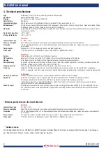
Automotive 7inch TFT liquid crystal display module LED backlight.
Resolution
WVGA 800xRGBx480 pixels.
Viewing
70° horizontal and 60° vertical (@ CR≥10).
LED Life Time
30000 Hrs.
Typical performance
Center luminance of white: 600cd/m2, Contrast ratio 650:1, Response time 5 ms (Tr).
Softwaremenu
Full On-Screen-Display (OSD) functionality in 15 languages: English, Dutch, German, French, Chech, Hungarian, Italian, Polish,
Portuguese, Spanish, Turkish, Swedish, Finnish, Danish, Norwegian.
ABC mode
Improved Auto Brightness Control (ABC) including one-touch day/night setting and adjustable minimum and maximum levels
for automatic control.
Operating temperature
-40°C ..+85°C.
Storage temperature
-40°C ..+105°C.
Electrical
Input voltage range
12...60V
+/-10%.
Power consumption
Max 12W (only for the monitor, total power consumption depending on cameras and other peripherals).
Protection
>70V overvoltageprotection, <10V undervoltageprotection, protected against loaddumps, spikes and surges, reverse polarity
on all wiring.
Power-output
Nominal 2A +/-10% for powering cameras and other peripherals.
Video input
1Vtt, 75
Ω
, Pal 50 Hz, 4,43MHz color sub carr. NTSC 60 Hz, 3,58MHz color sub carr.
Mechanical
Surface
Hard coating (3H), with AG LR (Low Reflection) polarizer.
UV Resistance
Exposure to intense direct sunlight (UV radiation) may increase the degradation of the display.
Housing
Color Black, material: aluminium & high impact automotive synthetic thermoplastic polymer.
Shock constancy
Shock and vibration resistant for usage on trucks, cranes, fork-lifts, maritime applications, machinery. Random vibration test
9,73Grms at frequency: 5 to 2000, PSD (g²/Hz) 0,015 to 0,10.
Ingress protection
IP67 according IEC 60529 (dust tight, immersion in water up to 1m for 30 min).
Truck use
Withstand all fluids and materials used in and around trucks like: ammonia solution 5%, ethanol 80-100%, isopropanol
5-10%, soapy water (min. 50% soap per volume), alkaline degreasing compounds(used in high pressure washing equipment).
Certification
Quality & environment
Units are manufactured by Orlaco in the Netherlands; ISO 9001, ISO14001, ISO-TS16949.
Approvals
Approvals in compliance with all relevant EMC- and Automotive directives. Certificates available upon request.
This device complies with Part 15 of the FCC Rules. Operation is subject to the following conditions:
(1) this device may not cause harmful interference, and (2) this device must accept any interference received, including
interference that may cause undesired operation.
Green Passport
All materials are compliant to Green Passport requirements according IMO resolution MEPC.197(62) as adopted on 15 July
2011 (Maritime sector: International Maritime Organization concerning the functions of the Marine Environment Protection
Committee).
Electrical
Input voltage range
18...30V
+/-10%.
Power consumption
Max 12W (only for the monitor, total power consumption depending on cameras and other peripherals)
Protection
>70V overvoltageprotection, <10V undervoltageprotection, protected against loaddumps, spikes and surges, reverse polarity
on all wiring.
Power-output
For powering cameras and other peripherals. Power-output = input voltage. Output current 2A max.
Video input
1Vtt, 75
Ω
, Pal 50 Hz, 4,43MHz color sub carr. NTSC 60 Hz, 3,58MHz color sub carr.
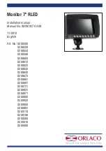
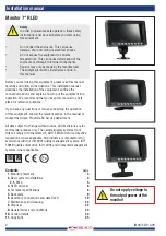
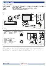
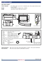
Installation manual
4. Technical specifications
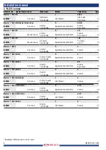
*Different specifications for the Serial Monitors
*
** Software menu
For the Radar Monitor Art. no. 0208871 and 0209110 applies; Software Menu Full On-Screen Display (OSD) functionality in 8 of langua-
ges: English, Dutch, German, French, Italian, Polish, Spanish, Swedish.
**