


32
IM0973270 A 09
Installation manual
4
1
2
3
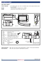
Back side
Solder side 8p male connector: (Secure the power input with a 5A fuse)
1 = Red
= Power input: 12...60V/DC
2 = White
= Power input: 0V
3 = Blue
= Cam No. 1 activated at 7...60V/DC*
4 = Brown
= Cam No. 2 activated at 7...60V/DC*
5 = White/Yellow = Cam No. 3 activated at 7...60V/DC*
6 = Grey
= N.C.
7 = Yellow
= N.C.
8 =
= N.C.
*Triggers camera >7V/DC and returns to non triggered <5V/DC.
If multiple cameras are triggered the highest cam. no. has the highest priority.
Solder side 4p female connector:
1 = Coax core
= Video in
2 = Coax shielding = Video 0V
3 = Red
= Power output: 12V/DC
4 = Black
= Power output: 0V
Shielding
= Ground
Connectors fixed on the back side of the monitor.
8
2
4
1
6
5
3
7
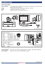
Connect instructions:
Please refer to your Orlaco system documentation or chapter 2. “Basic System Installations”
User instructions:
Please refer to User manual no: UM0972080 for operation.
Article number: 0209310
Cables / Connectors
0,24m multicable (power) with 8p male connector, 0,29m multicable (video) with 4p female
connector Art. no.:1001409
Weight
1,5kg (Monitor, cables and connectors)
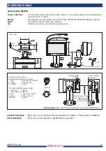
120
units in mm
188
98,3
49,1
89,6
Min. bend radius= 50mm
R = 50
89,6
118


