background image

36

Connection to other equipment

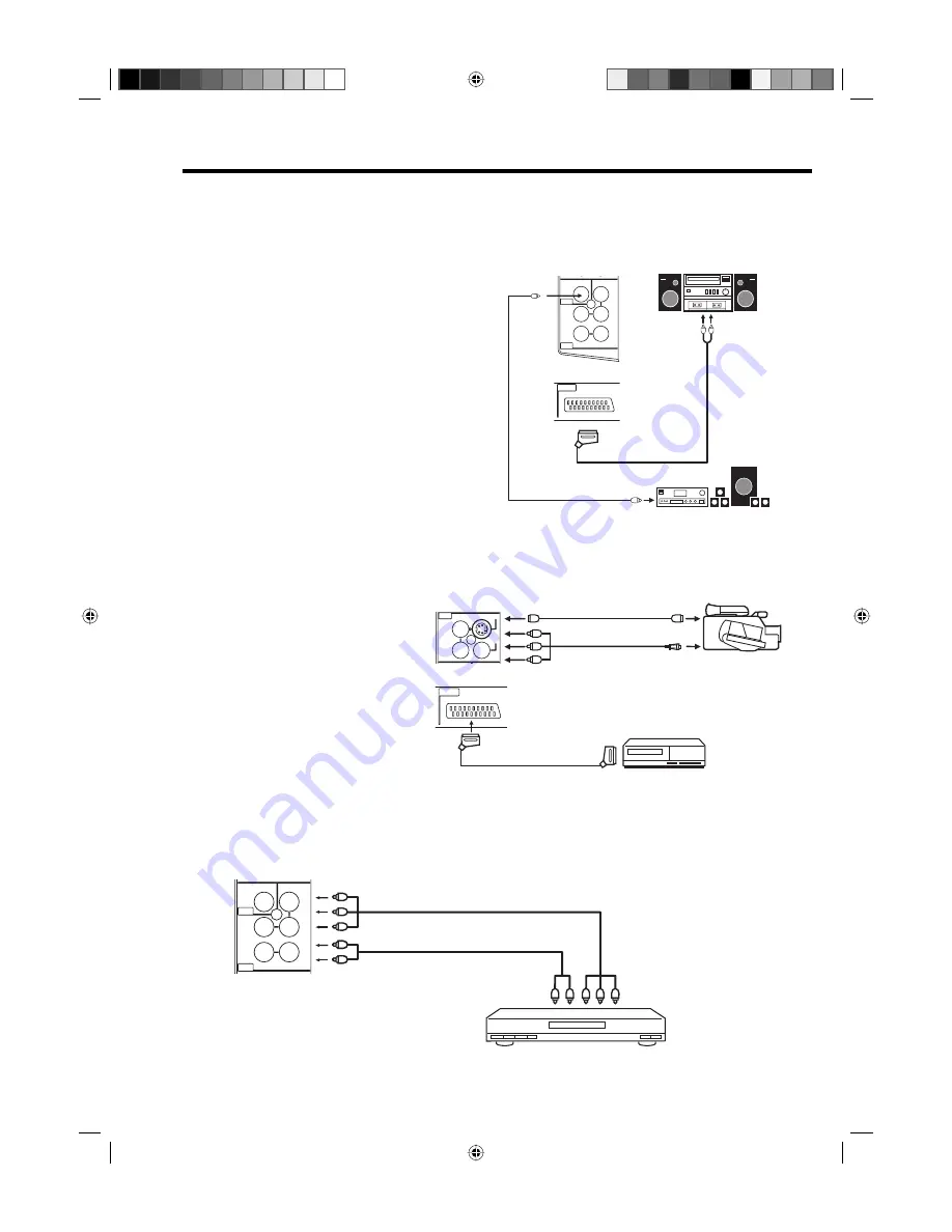
3.  Connecting an audio system

  You can supply the TV sound to the stereo equipment (A) with the scart socket. Use a special scart cable 

for the connection which sold at the accessory shop. (please consult your hi-fi instructions for details). 

If you have a surround sound amplifier/decoder (B) with a coaxial digital input, you can connect the 

Coaxial Digital Audio Output to it, using a suitable coaxial digital lead. This connection carries the audio 

signal from this set’s Digital channels only.

Note: 

The Bass/Treble/Balance adjustments (see 

P.21) only function with the sound from the TV 

speakers - it does not affect the audio output 

sockets.

(A)

(B)

TV (Left side view)

TV (Back side view)

Stereo amplifier

Audio input

(Coaxial digital lead, not supplied)

Surround sound amplifier system

COAXIAL

AUDIO OUT

(Scart-RCA cable, not supplied)

IN

AUDIO

L

Pb

OUT

DVB-T DIGITAL

AUDIO

OUT

COMPONENT

Pr

Y

R

R

(MONO)

AUDIO

VIDEO

AV 2

AV 1

IN

PC/HDMI

AUDIO

PC MONITOR

HDMI

SCART

5.  Connecting to a DVD player or other AV device with Component Video outputs

  If your DVD player (or other device) has Component Video output jacks, use a suitable set of leads (RCA/

Phono) to connect these to the Component Video inputs on this TV as shown - it can greatly enhance 

the picture quality and performance. Please remember that you will also need to connect separate leads 

(RCA/Phono) for the audio signals. Select the COMPONENT input mode (see P.12).

Y Pb Pr

IN

AUDIO

L

Pb

OUT

DVB-T DIGITAL

AUDIO

OUT

COMPONENT

Pr

Y

R

(MONO)

Component output

Audio output

Video cable (not supplied)

Audio cable (not supplied)

To COMPONENT IN

TV (Left side view)

Note:

The Component Video input of this unit are for use with equipment which outputs interlaced signals (PAL: 

576i/1080i or NTSC: 480i/1080i) and progressive signals (PAL: 576p/720p or NTSC: 480p/720p).    

DVD player

4.  Connecting Video camera and Video recorder

  Select the “MONITOR” option in the SETUP menu (see No.6 on page 37).

  Select the AV2 input mode (see P.12). You can see the playback picture from video camera.

  This signal is output via AV1 and can be recorded by video recorder.

  With this arrangement, Video recorder will record exactly what is shown on the screen.

 Note:

  •  If you have a camcorder with 

   S-video, use an S-video cable  

   instead of a standard video cable.  

   Do not connect both a standard  

   video cable and an S-video cable  

   at the same time, or the picture

   performance will be unacceptable.

  •  When you input the PAL-M signal  

   to AV2 input, select AV COLOUR  

   setting to AUTO, otherwise the   

   monochrome images will be    

   displayed.

IN

L

R

AUDIO

VIDEO

S-VIDEO

AV 2

(MONO)

Video camera 

to AV2

Playback

TV (Left side view)

TV (Back side view)

(AV cable, not supplied)

(S-VIDEO cable, not supplied)

AV output

AV 1

IN

PC/HDMI

AUDIO

PC MONITOR

HDMI

SCART

Video recorder 

to AV1 

Recording

(SCART cable, not supplied)

32G0146B_ENG.indd   36

32G0146B_ENG.indd   36

10/11/07   1:52:33 PM

10/11/07   1:52:33 PM

Summary of Contents for TV19PL110D A

Page 1: ...erating Instructions Before operating the unit please read this manual thoroughly Digital LCD Colour Television TV19PL110D 32G0146B_ENG indd 1 32G0146B_ENG indd 1 10 11 07 1 52 09 PM 10 11 07 1 52 09...

Page 2: ...ion for the DVB T function Any function relative to the digital television with the DVB logo is available only within the country or area where such signals are transmitted Verify with the salesman if...

Page 3: ...r 17 Picture size and resolution 18 Picture format 19 Other convenience functions 21 Remarks on DVB T system 22 Language Setup 23 Auto Scan 23 Manual Scan 24 Carrier Setup 24 Channel Organizer 25 Disp...

Page 4: ...rs should be put on the unit The remote control is not a toy Toddlers could swallow the batteries If a battery has been swallowed please seek out a doctor immediately The screen is made of glass and c...

Page 5: ...tors Do not place in direct sunshine When placing on a shelf leave 10 cm free space around the whole unit Make some space around TV Correct shelf assembly The apparatus shall not be exposed to drippin...

Page 6: ...grained in the LCD TV panel and cause subtle but permanent ghost images This type of damage is NOT COVERED BY YOUR WARRANTY Never leave your TV on for long periods of time while it is displaying the f...

Page 7: ...ENT HDMI PC In Menu Using as ENTER button 8 Power key Preparation Connect power cable to 230V 50Hz a If standy LED is red you may power off To power off press power key 1x and release For confirmation...

Page 8: ...f 15 Exit the menu screen Volume 15 Change the TV channel or Teletext page up or down In Standby Turn on the power 15 16 12 Cursor buttons Memorize Teletext page 100 CH LIST 16 15 Toggle between the T...

Page 9: ...pen the battery compartment 2 Install the batteries as shown below ensuring the correct polarity 3 Close the battery compartment The remote control handset will not work properly in the following case...

Page 10: ...ni plug 3 5 mm into this jack E AV2 input Input for analogue A V Signal Composite or S Video See P 36 F COMPONENT input See P 36 G Digital audio output digital output for DVB T sound see page 36 H PC...

Page 11: ...TV will now automatically tune in all available channels Your TV will tune the analogue channels first then tune the digital channels Note Please be patient the Auto Tuning process can take several m...

Page 12: ...ERTICAL POSITION 0 AUTO 4 3 DEFAULT 16 9 3 Press or to select AUTO TUNING then press ENTER to enter the AUTO TUNING menu on the following pages the MENU can be called in the same way as here AUTO TUNI...

Page 13: ...you wish 1 Select CH ALLOCATION Then press ENTER AUTO TUNING MANUAL TUNING CH ALLOCATION LANGUAGE ENGLISH VERTICAL POSITION 0 AUTO 4 3 DEFAULT 16 9 2 Select desired option then press ENTER SORT ERASE...

Page 14: ...key again to continue tuning for the ZDF Then press ENTER SEARCH FINE 168 30MHz COLOUR SYSTEM AUTO SOUND SYSTEM AUTO ZDF 175 30MHz 5 If you like use fine tuning Select FINE and press ENTER Press or to...

Page 15: ...t QuickView button allows you to go back to the last selected channel Volume adjusting Press or to adjust the volume The volume level indicator disappears after 4 seconds MUTE Press The sound will be...

Page 16: ...appears Or enter the requested page number by using the 10 Number Buttons And if you mistype something just enter the com plete 3 digit wrong page number then enter the de sired number again Or press...

Page 17: ...A broadcast signal is received NICAM M1 M2 illuminates for approx 4 seconds when a NICAM MONO A and MONO B broadcast signal is received This will be displayed for approx 4 seconds if a NICAM signal i...

Page 18: ...ived E g 4 3 A 4 3 displays vertical black bars to the right and left If a 4 3 picture is increased then it either appears distorted see image or some of the picture is cut off at the top and bottom T...

Page 19: ...st receive an anamorphic 4 3 picture This picture is pre distorted accordingly before being broadcast see figure 1 After the TV receiver has uncompressed the anamorphic picture to the full 16 9 width...

Page 20: ...rder as in the illustration this is a 4 3 letterbox signal Limited by the broadcasting station the set operating this signal is much too low for a 16 9 HD ready screen CINEMA increases this picture th...

Page 21: ...ctory preset values NICAM See page 17 BASS TREBLE BALANCE You can adjust the sound quality to your preference HDMI AUDIO See page 34 RESET Select RESET to reset BASS TREBLE and BALANCE to the factory...

Page 22: ...Visible interference e g blocky picture can result at extremely low data rates despite there being excellent reception quality within vicinity of the transmitter Blocky pictures are no fault of the r...

Page 23: ...n Please ensure that all the connections have been made correctly see page 10 1 Press or to select Auto Scan then press ENTER Manual Scan Auto Scan Carrier Setup n o i t a l l a t s n I u n e m n i a...

Page 24: ...t Channel List Type Select the Channel List Type by pressing and press ENTER If FINLAND is selected on the AUTO INSTALLATION COUNTRY screen Data is displayed on the Carrier Setup screen Carrier Setup...

Page 25: ...llowing functions from this menu for each channel Favourite Lock Skip Go To Delete Rename Move Move to and View You can deactivate each of these functions by pressing the same number again See page 26...

Page 26: ...lete the selected service s from the memory Press to select the desired service Press 5 on the remote control An icon displays indicating the service to be deleted Pressing 5 will turn the delete icon...

Page 27: ...sword Setup Parental lock This feature allows you to have a parental control of the service viewing as per your preference Once a service is protected with a password it cannot be viewed unless the co...

Page 28: ...ally If you select the option No you can continue to watch TV programmes as before Note During the Software Updating process do not turn off the unit At this time you cannot use any of the buttons apa...

Page 29: ...enu information such as current date time channel name etc will be displayed 1 While watching the service press to display the Channel banner at any time It will disappear after the Banner timeout val...

Page 30: ...list Multi audio Audio mode Navigate Enter Exit No Language Code 001 ENG L R 3 Press EXIT Your selected audio preferences will be saved DVB Subtitle DVB Subtitle is a feature supported in DVB Digital...

Page 31: ...ssing or the Event list will be refreshed accordingly and you will see the programme information for the currently highlighted programme To scroll through the service list page by page press Red or Gr...

Page 32: ...Down Nigel and Eliza are on their way to film a rare fish Nigel suggests a shortout through a bog but Ellza is reluctant Th 16 30 17 00 The Wild Thornberrys CBBC 7 0 0 2 8 0 0 2 n u S E N O C B B 1 0...

Page 33: ...witch off your TV and disconnect from the 230V power supply Disconnect the digital PCconnection Now you may retry operating your TV If a digital PC connection does show a picture proper working is not...

Page 34: ...input source You must choose the appropriate HDMI audio input setting for each connection depending on whether the source is equipped with a DVI or HDMI socket 1 Select HDMI AUDIO then press ENTER Pre...

Page 35: ...ctions are properly and correctly attached before connecting the appliances to the power supply Connect with Satellite receiver as shown below Select the TV Program at the satellite receiver To do thi...

Page 36: ...ct separate leads RCA Phono for the audio signals Select the COMPONENT input mode see P 12 Y Pb Pr IN AUDIO L Pb OUT DVB T DIGITAL AUDIO OUT COMPONENT Pr Y R MONO Component output Audio output Video c...

Page 37: ...stment The AV Colour setting only applies when viewing devices connected to the AV inputs 1 In select AV COLOUR then press ENTER 2 Press or to select AUTO AV1 OUTPUT AV COLOUR AUTO AUTO REC SCREEN STA...

Page 38: ...tuning again 23 The LCD panel is a very high technology product giving you fine picture details Occasionally a few nonactive pixels may appear on the screen as a fixed point of blue green or red Plea...

Page 39: ...32G0146B_ENG indd 39 32G0146B_ENG indd 39 10 11 07 1 52 35 PM 10 11 07 1 52 35 PM...

Page 40: ...J32G0146B SH 07 12 P 32G0146B_ENG indd 40 32G0146B_ENG indd 40 10 11 07 1 52 35 PM 10 11 07 1 52 35 PM...

Reviews: