background image

- 30 -

ORION PDP

- 31 -

Infinitely Expandable 

Multi-screen configuration
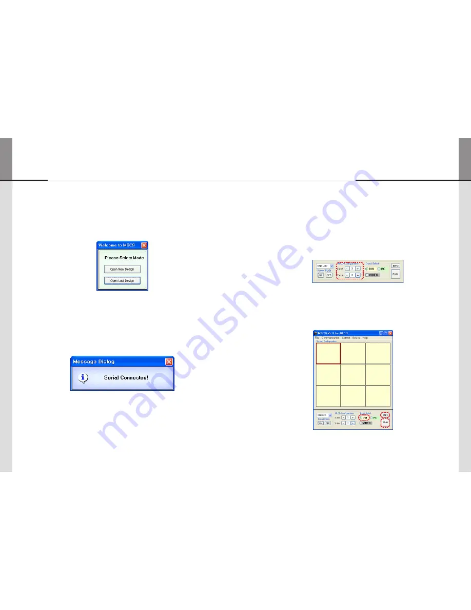
5.6. 

Input the numbers of X and Y  

 1. 

X is for the number of row and Y is for column.


-

X and Y can be selected within the range from 1 to 15. The maximum MLCD quantity of MSCS 


-

control is 100 sets.
MLCD image of selected numbers of X and Y is displayed in the Screen configuration in one 


-

second after setting the number.

ScreenConfigurationSetting

Select one of input sources from DVI, PC or Video 

 2. 

Execution of the configuration.

 3. 

When you click "PLAY"button after selecting input source from Source select and the numbers of 


-

X and Y in MLCD Configuration, the configuration of MLCD is generated as shown in the figure 
below. 


inFO


 : 

Check the resolution of the input source. It is displayed at the upper right corner of the screen.


-

Check the signal. If there is no input signal, "No signal" is displayed.


-

DVI

DVI

DVI

DVI

DVI

DVI

DVI

DVI

DVI

"new design/Last design" setting

5.5. 

WhenComPortissuccessfullyconnected,pop-upwindowfor"Newdesign/Lastdesign"

y

appears.

New/LastDesignSet

Click"OpenNewDesign"topreparenewconfiguration.

y

Click"OpenLastDesign"togotolastdesignbeforeclosing.

y


WhentheconnectionissuccessfullycompletedaftersettingComPort,following

y

Messagedialogisdisplayed.Thedialogwindowwillbedisappearedin1second.

MLCD

Summary of Contents for ODC-10000

Page 1: ...s product This product is manufactured for Multi LCD model only User s Manual OLM 5550 Infinitely Expandable MLCD A revolutionary MLCD A revolutionary MLCD Infinitely Expandable MLCD Address 257 6 Gon...

Page 2: ...manufacturer s instructions 8 Do not install near any heat sources such as radiators heat registers stoves or other apparatus including amplifiers that produce heat 9 Do not defeat the safety purpose...

Page 3: ...cket therefore the mains plug shall be readily operable 2 WARNING To Reduce The Risk Of Fire Or Electric Shock Do Not Expose This Appliance To Rain Or Moisture 3 Apparatus shall not be exposed to drip...

Page 4: ...ice If service people can step into the backside of MLCD system it can greatly reduce time and effort for service In case of higher locations consider the installation location and exterior design for...

Page 5: ...k and lean over the LCD to avoid panel touches ground or floor Please do not lean over the LCD It may damage the bottom part of the LCD If you need to lay down LCD as face down position please use sho...

Page 6: ...areful not to touch the bottom part of the panel when you put down the panel It always needs two persons to carry or install MLCD When you carry MLCD with up straight manner please hold handles on the...

Page 7: ...y object If the ventilation hole is blocked the inside temperature may rise to cause overheating resulting in fire Do not poke the front screen with sharp material It may damage the screen and may cau...

Page 8: ...Around high voltage power lines Noise from the power line may affect screen images Around heating apparatus LCD set may be overheated and damaged Guide Pin Hanger Hanger Bolt LCD MAIN FRAME 20cm 20cm...

Page 9: ...d If power cable is not disconnected during ID setting MLCD set may be operated with the previous ID and it may cause abnormal behavior For stable operation wait for at least 10 seconds prior to use M...

Page 10: ...Screen adjustment can be controlled by MSCS Multi Screen Control y y System ID setting on the backside of MLCD must be identical with the ID setting in MSCS to control y y MLCD with a PC If you do not...

Page 11: ...STB PWR ON VIDEO IN OUT DVI D IN OUT RS 232C IN OUT PC IN OUT LAN SVC ID SELECT Connection of Multiple MLCD 4 2 RS 232C PC DVI MLCD 1 MLCD 2 Recommended maximum set connection for Multi setting is sho...

Page 12: ...OUT RS 232C IN OUT RS 232C IN OUT RS 232C IN OUT RS 232C IN OUT RS 232C IN OUT RS 232C IN OUT RS 232C IN OUT RS 232C IN OUT RS 232C IN OUT RS 232C IN OUT RS 232C Distributor RS 232C control PC ID 1 I...

Page 13: ...2 3 4 5 6 7 8 9 0 1 2 3 4 5 6 7 8 9 0 1 2 3 4 5 6 7 8 9 0 1 2 3 4 5 6 7 8 9 0 1 2 3 4 5 6 7 8 9 0 1 2 3 4 5 6 7 8 9 0 1 2 3 4 5 6 7 8 9 0 1 2 3 4 5 6 7 8 9 0 1 2 3 4 5 6 7 8 9 0 1 2 3 4 5 6 7 8 9 0 1...

Page 14: ...ht button of your mouse on the desired MLCD set from MSCS Please do not use above function together with the other functions 2 When you off AC power execute power off by MSCS first and disconnect AC p...

Page 15: ...rs you need to set Com Port again because MSCS uses one of Com Port no 1 to 30 Available Com Port on the PC is automatically recognized and displayed Com Port Configuration y y Baud Rate 115200bps Fix...

Page 16: ...atus of communication 5 Close the Commnication setup window Menu Description Serial y y Set the serial communication as a default communication Com Port y y Set the port of a PC to communicate with ML...

Page 17: ...elect and the numbers of X and Y in MLCD Configuration the configuration of MLCD is generated as shown in the figure below Info Check the resolution of the input source It is displayed at the upper ri...

Page 18: ...er On command after the first AC power connection If not it may cause abnormal behavior Please disconnect AC power and reconnect in case of abnormal behavior Caution Changing the input source 5 8 Vari...

Page 19: ...of the mouse DVI screen will be changed with PC PC DVI DVI DVI PC DVI DVI DVI DVI Screen Formation with one step 3 You can make various multi screen formations with simple movement y y Select an input...

Page 20: ...on Time in Slide Control 2 Click Add button to save configuration The range of Operation Time is from 10 seconds to 1 hour DVI DVI DVI DVI DVI DVI DVI DVI DVI DVI DVI DVI DVI DVI DVI DVI DVI DVI Save...

Page 21: ...y of MLCD can be changed y y To use Picture Control go to MSCS Menu Control Picture Control or press Ctrl P y y using Keyboard In order to control display values input values directly in Edit Box and...

Page 22: ...ct PC Connect Ethernet Connect USB Connect AS Connect MLCD N x M Configuration New MFC Front HOR VER Control Method of optional accessory 6 New MFC 6 1 New MFC Connection 1 Connect power 1 Connect fem...

Page 23: ...OADCAST ID SETTING ON OFF 1 2 3 4 5 6 7 8 0 9 DVI 1 DVI 2 OUTPUT FUNCTION DVI CONVERTER INPUT MPDP MLCD Set Configuration e g X 5 sets x Y 6 sets 2 Vertical configuration Press SET button 1 SET Press...

Page 24: ...D of DVI Converter The ID can be selected from 1 to 9 y y CMND 2 Select the channel of DVI converter to control y y One of DVI Channel 1 DVIC1 DVI Channel 2 DVIC2 and ALL DVI Channel can be y y select...

Page 25: ...Set or change the screen ratio Horizontal Vertical y y y y 16 9 Set the screen ratio as 16 9 wide screen 4 3 y y Set the screen ratio as 4 3 LB Letter Box y y Expand the screen image to remove the bla...

Page 26: ...Pattern Red Blue 8 Color 16 Gray Green White White 10 Screen y y Set y y Set or change the Pattern Lock FreeRun 11 Lock y y Default setting It is used when MLCD is configured as the default display I...

Page 27: ...PIP click PIP in the Mode The position of sub picture can be controlled by clicking buttons increase or decrease the number or directly type in the numbers at Edit box Various input sources can be us...

Page 28: ...eans Broadcast command variable MSCS Protocol 7 Master 0x01 This is the scaler code ETX 0x03 The end of the code Fixed value Receive From LCD 2 2 STX CMD Length Data Check Sum ETX 1 byte 1 byte 1 byte...

Page 29: ...atio Full screen is 0x11 S The ID of MLCD to be expanded in top left position 1 1 screen ratio Full screen is 0x00 X The number of all X axis line 1 1 screen ratio Full screen is 0x01 Make all LCD do...

Page 30: ...able 0x02 Variable 0X01 Variable 0x03 ID range Program 0x01 1 0xFF 255 Check Sum execute Not operation after adding all the values in STX Data area Auto Power Mode 3 7 Configuration for automatic powe...

Page 31: ...FF 255 Broadcast Command B STX CMD Length Data ID ETX Value 0x02 Variable 0x01 0x00 0x03 Make all LCD do the same operation But there will be no return communication One way command Receive from MLCD...

Page 32: ...set On 6 Color Temp 1 byte 0 Normal mode 1 Studio mode 7 Auto Power Mode 1 byte 0 Auto Power Off 1 Auto Power On 8 FAN Mode 1 byte 0 Auto 1 Full 9 Temperature0 1 byte 0 0x00 0 C 127 0x7F 127 C 128 0x8...

Page 33: ...e will be no return communication One way command Receive from MLCD STX CMD Length Data Check Sum ETX ID Master Value 0x02 Variable 0x02 Variable 0X01 Variable 0x03 ID range Program 0x01 1 0xFF 255 Ch...

Page 34: ...2byte Range 0 0x000 1023 0X3FF 14 15 RGB Gain G 2byte Range 0 0x000 1023 0X3FF 16 17 RGB Gain B 2byte Range 0 0x000 1023 0X3FF 18 19 RGB Offset R 2byte Range 0 0x000 1023 0X3FF 20 21 RGB Offset G 2by...

Page 35: ...Data adjusted in the factory This is different from CMD 0x82 Save 0x83 Load It is usable only at Power on Operative It shows the value based on current Color Temp Normal Mode Studio Mode Data can be...

Page 36: ...t affect product s performance No image at upper and lower part of the screen As for a screen which is over 16 9 in width such as cinema sized one no image y y may be displayed at upper and bottom par...

Page 37: ...0 858 720 62 62 525 480 6 30 EDTV 576p 50 31 250 27 000 864 720 64 68 625 576 5 39 EDTV 720p50 50 37 500 74 250 1980 1280 80 220 750 720 5 20 HDTV 750p60 60 45 000 74 250 1650 1280 80 220 750 720 5 20...

Page 38: ...Display C LCD 2X16 Input Souce Output Resolution Display Specification can be changed without prior notice to improve product quality Ethernet communication is available when it is used with New MFC N...

Reviews: