background image

Machine Manual

Orion

Flex Stretchwrapper

Revision 3.0

Troubleshooting

15 February 2016

Page 4-2

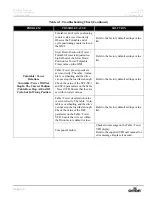
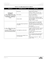
Turntable / Tower 

Rotation-

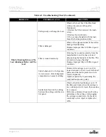
Turntable / Tower Will Not 

Stop In The Correct Position. 

(Table Does Stop At End Of 

Cycle-but In Wrong Position

Turntable end of cycle positioning 
counter value is set incorrectly. 
Observe the Turntable end of 
cycle positioning counter value on 
the HMI. 

Refer to the factory default settings value 
list. 

Slow Down Position for Tower /
Turntable Timer is adjusted too 
high. Observe the Slow Down 
Position for Tower /Turntable 
Timer value on the HMI. 

Refer to the factory default settings value 
list. 

Table / Tower preset speeds are 
set incorrectly. The table  / turnta-
ble is overhauling and the drive 
can not stop the load fast enough. 
Check the value of the SP-2-SP-3 
and SP-4 parameters on the Table 
/ Tower VFD. Ensure that they are 
set within correct values.

Refer to the factory default settings value 
list. 

Table / Tower deceleration value 
is set incorrectly. The table  / turn-
table is overhauling and the drive 
can not stop the load fast enough. 
Check the value of the DEC 
parameter on the Table / Tower 
VFD. Ensure that it is set within 
the Orion factory default values.

Refer to the factory default settings value 
list. 

Component failure.

Check error message on the Table / Tower 
VFD display.
Refer to the supplied VFD user manual for 
error message. Replace if needed.

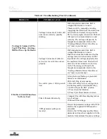
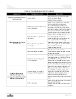
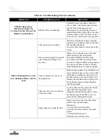
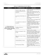
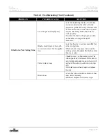
Table 4-1. Troubleshooting Chart (Continued)

PROBLEM

POSSIBLE CAUSE

SOLUTION

Summary of Contents for FLEX HPA

Page 1: ...2016 Machine Manual Revision 3 0 To Navigate Contents In Acrobat Choose View Navigation Panes Make sure Bookmarks are Checked May vary slightly depending on your version of Acrobat 4750 County Road 1...

Page 2: ...rty of the author who created the work Pro Mach Only the author or those deriving their rights through the author can right fully claim copyright Liability Waiver The information in this manual is sub...

Page 3: ...rd Messages 1 6 Operation Safety 1 7 Maintenance Safety 1 8 Lockout and Tagout Recommendations 1 9 Electrical System 1 9 Pneumatic and Vacuum Systems 1 10 Installation and First Time Power Up 1 11 Unl...

Page 4: ...3 15 Recipe Screen 3 17 Production Data Screen 3 18 Recipe Viewing Screen 3 19 Machine Settings Screens 3 20 Machine Settings Screen 3 20 Main Drive Screen 3 22 Reinforce Wrap Setup 3 23 Timers Scree...

Page 5: ...es 5 6 5 760 Loads or one month 5 6 17 280 Loads or three months 5 6 All H L Heavy Duty Ring Bearing Series 5 7 5 760 Loads Or One Month 5 7 17 280 Loads or three months 5 7 34 560 Loads or 6 months 5...

Page 6: ...Machine Manual Orion Flex Stretchwrapper Revision 3 0 Table of Contents 15 February 2016 Page IV...

Page 7: ...itch Alignment 3 2 Loading the Film 3 3 The Run Screen 3 5 The Maintenance Prompt Screen 3 7 The Security Settings Screen 3 9 The Wrap Settings Screen 3 10 The Menu Screen 3 12 The Jogging Screen 3 13...

Page 8: ...Outputs Screen 3 41 The VFD Diagnostics Screen 3 42 The HMI Setup Screen 3 43 The Maintenance Log Screen 3 44 The Fault History Screen 3 45 Setting the IP Address 3 46 Flex Dashboard 3 47 Chapter 4 T...

Page 9: ...ight Notice 1 2 Flex Series Warranty 1 3 Safety 1 4 System Safety Recommendations 1 5 Hazard Messages 1 6 Operation Safety 1 7 Maintenance Safety 1 8 Lockout and Tagout Recommendations 1 9 Pneumatic a...

Page 10: ...Machine Manual Orion Flex Stretchwrapper Revision 3 0 Introduction and Safety Contents 15 February 2016 Page II...

Page 11: ...ad this manual carefully and keep it handy Following these simple operating instructions will insure the safe and efficient performance of this machine while simple maintenance procedures will guarant...

Page 12: ...erator control panels the Human Machine Interface and operational procedures Section 4 is the Troubleshooting section A Troubleshooting chart is found in this sec tion Section 5 is the Maintenance sec...

Page 13: ...port is the responsibility of the carrier and is not covered under our warranty FREIGHT CHARGES There will be no freight charges for warranty parts that are ordered for shipment via UPS regular ground...

Page 14: ...ing equip ment To achieve this our machines must be efficient easy to maintain and safe to oper ate Before attempting to operate the equipment become familiar with the safety recommen dations and oper...

Page 15: ...s removed Do not wear neckties loose clothing or long loose hanging hair around any equip ment Observe and follow the DANGER WARNING and CAUTION messages throughout this manual in vendor manuals and d...

Page 16: ...personnel or equipment These messages convey three levels of risk as defined below Failure to observe these instructions can result in death serious injury damaged equipment or loss of product or prod...

Page 17: ...ator should understand the complete task that the system is designed to accomplish The operator should know the location and functional status of all devices switches sensors control signals that can...

Page 18: ...rom injury and to indicate the equipment is being serviced Place a lock on the main electrical disconnect as shown below while performing maintenance Personnel should pay careful attention to all devi...

Page 19: ...maintenance each individual shall install a lockout device and tag A qualified person shall verify that the equipment is de energized by 1 Operating controls to verify equipment cannot be restarted 2...

Page 20: ...r locking out the system If several personnel are performing maintenance each individual shall install a lockout device and tag Qualified personnel shall vent any stored or accumulated air in pneumati...

Page 21: ...ing tubes to the maximum possible depth Depending on the model a forklift access may be either at the tower end of the machine frame the tower end or both Look for the forklift tube access stickers sh...

Page 22: ...Motors and transmissions Junction boxes Electrical conduits Proximity and limit switches Photocells 3 Check around the tower to ensure that there is no crippling of the movable parts i e casters cente...

Page 23: ...have to be installed on a lev eled floor The base deviation from vertical must not exceed 1 4 on the distance of 10 feet angle 0 degrees 6 Move the wrapper into its final position If the wrapper is t...

Page 24: ...serve safety precautions in the user manual Always follow OSHA and plant regulations when placing machinery 1 Attach a strap around the center crossmember Secure to properly rated lifting device 2 Rai...

Page 25: ...16 Introduction and Safety Page 1 15 3 Your spotter can position the machine precisely while the lift is holding the tower ver tically 4 Remove the shipping feet while the machine is still held by the...

Page 26: ...16 5 Using a hammer drill drill the mounting holes in the floor with the correct drill bit to match the mounting hardware 6 Pound in the 10 Red Head Anchors Use 5 8 hardware The length of the anchors...

Page 27: ...pper 15 February 2016 Introduction and Safety Page 1 17 7 Once the machine is properly bolted down loosen the tension to the crossmember 8 Climb the ladder and remove the strap Figure 1 8 Loosen Tensi...

Page 28: ...hwrapper Revision 3 0 Introduction and Safety 15 February 2016 Page 1 18 9 Bolt the safety hoop to the bottom of the rotary arm 10 Verify the machine is properly secured and test the machine operation...

Page 29: ...Orion Machine Manual Revision 3 0 Flex Stretchwrapper 15 February 2016 System Description Contents Page I System Description Contents Machine Specifications 2 1...

Page 30: ...Machine Manual Orion Flex Stretchwrapper Revision 3 0 System Description Contents 15 February 2016 Page II...

Page 31: ...e Web based Production Data Dashboard Optional Wireless Connection to the PLC HMI Downloadable VFD Parameters Variable Speed Film Carriage Up Down Control Film Carriage Manual Jog Functionality Photoc...

Page 32: ...y 2016 Page 2 2 Variable Frequency Drive Motor Multi point Uhmw Precision Carriage Guidance System Structural Features Structural Steel Construction Throughout Easy Access To All Components Limited Pr...

Page 33: ...Data Screen 3 18 Recipe Viewing Screen 3 19 Machine Settings Screens 3 20 Machine Settings Screen 3 20 Main Drive Screen 3 22 Reinforce Wrap Setup 3 23 Timers Screen 3 24 Machine Setup Screen 3 26 St...

Page 34: ...Machine Manual Orion Flex Stretchwrapper Revision 3 0 System Operation Contents 15 February 2016 Page II Alarm Displays 3 52...

Page 35: ...two settings ON connects a power source to the machine OFF disconnects the power source START AND EMERGENCY STOP SWITCHES Press the START button to gain Control Power prior to starting The START switc...

Page 36: ...cle detect error occurs the brake must be released 2 To release the brake pull outward on the carriage strap on the front side of the tower until the brake releases 3 Align the limit switch on the ins...

Page 37: ...e threading door is open When opened it will set off an alarm on the HMI and prevent the car riage from moving 6 Pass the roped tail of the film through opening 7 Close the carriage door Ensure the la...

Page 38: ...this button to go to the Run Screen The icon will illuminate in green when the screen is currently active Press this button to go to the Wrap Settings Screen The icon will illuminate in green when the...

Page 39: ...to the home proximity sensor Figure 3 4 The Run Screen Table 3 2 The Run Screen Button Descriptions STATE 1 DESCRIPTION STATE 2 Press and hold this button to start the machine This must be held until...

Page 40: ...sed REINFORCING Press this button to toggle between High Speed and Low Speed operation When High Speed is selected the Main Drive will travel at the predefined High Speed value during the wrap cycle W...

Page 41: ...completed and reset the counter Press Snooze to delay the counter for 100 cycles before the prompt re displays Figure 3 5 The Maintenance Prompt Screen Table 3 3 The Maintenance Prompt Screen Button...

Page 42: ...TURNTABLE SUPPORT CASTERS FOR GOOD CONDITION 17 280 INSPECT TURNTABLE CHAIN APPLY LUBRICATION AS NEEDED 17 280 INSPECT ROTARY ARM CHAIN APPLY LUBRICATION AS NEEDED 17 280 INSPECT MULTISTRETCH CHAIN A...

Page 43: ...out on powerup or after the logout timer has expired USER LEVEL Press this button to set the Default Security level to User When selected the machine will automatically log in to the User security le...

Page 44: ...ns such as Wrap Bottom First Wrap Top First Low Speed High Speed Unstable Load Enabled or Disabled Autoheight Enabled or Disabled or Film Fault Enabled or Disabled You can view each pattern settings o...

Page 45: ...Speed value during the wrap cycle When Low Speed is selected the Main Drive will travel at the predefined Low Speed value during the wrap cycle HIGH SPEED SELECTED UNSTABLE LOAD DISABLED Press this b...

Page 46: ...HMI screens Figure 3 8 The Menu Screen Table 3 7 The Menu Screen Button Descriptions STATE 1 DESCRIPTION JOGGING Press this button to go to the Jogging Screen See Jogging Screen on page 3 13 RECIPES P...

Page 47: ...ging Screen Table 3 8 The Jogging Screen Button Descriptions STATE 1 DESCRIPTION Press this button to move the machine to the home position Press this button to jog the main drive turntable tower in t...

Page 48: ...until the operator releases the jog button Press this button to toggle through the film clamp stages Press this button to manually trigger the brush and cut sequence Press this button to reset faults...

Page 49: ...Button Descriptions STATE 1 DESCRIPTION CARRIAGE UP SPEED Press this button to modify the Carriage Up Speed in terms of percentage Min 5 Max 100 CARRIAGE DOWN SPEED Press this button to modify the Car...

Page 50: ...em Operation 15 February 2016 Page 3 16 Press this button to reset faults If you press this button while the machine is run ning the machine will abort the current wrap cycle Table 3 9 The Carriage Jo...

Page 51: ...ton Descriptions STATE 1 DESCRIPTION STATE 2 SELECT RECIPE Press a recipe button to choose between the different recipe wrap settings Changes made to a recipe are saved to the active recipe If you att...

Page 52: ...also reset the shift cycle counter Figure 3 12 The Production Data Screen Table 3 11 The Production Data Screen Button Descriptions STATE 1 DESCRIPTION LIFETIME CYCLES This display shows the number o...

Page 53: ...helpful for a quick glance at each recipe s parameters Figure 3 13 The Recipe Viewing Screen Table 3 12 The Recipe Viewing Screen Button Descriptions STATE 1 DESCRIPTION RECIPE Press the recipe name...

Page 54: ...in Drive Screen on page 3 22 REINFORCE Press this button to go to the Reinforce Screen See Insta Cut Screen on page 3 32 TIMERS Press this button to go to the Timers Screen See Insta Cut Screen on pag...

Page 55: ...3 21 INSTA CUT Press this button to go to the Insta Cut Screen See Insta Cut Screen on page 3 32 DUAL TURNTABLE Press this button to go to the Dual Turntable Screen See Dual Turntable Screen on page 3...

Page 56: ...r starts to decel before stop ping at home An earlier slow down position might be needed for heavier loads and a later slowdown position for lighter loads The value is the tooth count in which the mac...

Page 57: ...ser to set the number of reinforce wraps that are applied when the reinforce button on the Run Screen is pressed Figure 3 16 The Reinforce Setup Screen Table 3 15 The Reinforce Wraps Screen Button Des...

Page 58: ...TENSION ENGAGE DELAY Press this button to modify the Tension Engage Delay value in terms of millisec onds This value determines the amount of time at the beginning of the wrap cycle that the Multistr...

Page 59: ...button to modify the Hot Wire On Delay value in terms of milliseconds This value determines the amount of time after the Brush and Cutter arm has begun to extend that the Hot Wire will delay before tu...

Page 60: ...s button to select model A A MODEL SELECTED SELECT D MODEL Press this button to select model D D MODEL SELECTED SELECT S MODEL Press this button to select model S If S is selected and the machine is a...

Page 61: ...enabled the Rotary Arm will reverse to the Home Prox after the film was clamped and cut ARM BACKUP ENABLED SECURITY Press this button to go to the Security Settings Screen START DELAY Press this butto...

Page 62: ...must be pressed before the machine starts Figure 3 19 The Start Delay Screen Table 3 18 The Start Delay Screen Button Descriptions STATE 1 DESCRIPTION START DELAY Press this button to modify the Star...

Page 63: ...ctory Defaults Screen Table 3 19 The Factory Defaults Screen Button Descriptions STATE 1 DESCRIPTION RESTORE FACTORY DEFAULTS Press this button to delete the currently entered factory settings and rep...

Page 64: ...n 3 mA Max 8 mA GAIN Press this button to modify the Gain datapoint in terms of percentage This value sets percentage of deflection of the dancer bar that is required for the Multistretch to pay out f...

Page 65: ...current VFD as half horsepower drive 1 HP IDENTIFIED Displayed if the machine identifies the current VFD as a one horsepower drive SELECT VFD SIZE If the machine cannot automatically identify the size...

Page 66: ...nsta Cut puncher activates to punch a hole in the film Min 20 Max 96 or 112 depending on sprocket selection INSTA CUT PUNCH DWELL Press this button to modify the Insta Cut Punch Dwell This is the amou...

Page 67: ...HZ Press this button to modify the Insta Cut Speed This is the speed at which the Main Drive will travel during the Insta Cut sequence Min 8 Hz Max 27 Hz This indicator will glow green when the Insta...

Page 68: ...running the A and B tables every other cycle Figure 3 24 The Dual Turntable Screen Table 3 23 The Dual Turntable Screen Button Descriptions STATE 1 DESCRIPTION SELECT TABLE A ONLY Press this button to...

Page 69: ...table B This allows the operator to disable the Insta Cut function INSTA CUT TABLE B DISABLED A INSTA CUT PUNCH POSITION Press this button to modify the table A Insta Cut Punch Position This is the to...

Page 70: ...stay activated to create a hole in the film Min 2 Max 15 B INSTA CUT BRAKE POSITION Press this button to modify the table B Insta Cut Brake Position This is the tooth count position at which the Multi...

Page 71: ...ich the Insta Cut puncher activates to punch a hole in the film INSTA CUT PUNCH DWELL Press this button to modify the Insta Cut Punch Dwell This is the amount of teeth that the Insta Cut puncher will...

Page 72: ...etchwrapper Revision 3 0 System Operation 15 February 2016 Page 3 38 This indicator will glow green when the Insta Cut puncher is active Table 3 25 The Insta Cut S Screen Button Descriptions Continued...

Page 73: ...go to the Outputs Screen See The Outputs Screens on page 3 41 VFD S Press this button to go to the VFD s Screen See The VFD Diagnostics Screen on page 3 42 HMI Press this button to go to the HMI Scree...

Page 74: ...ns This is the Inputs screen This screen shows the status of the machine inputs There is another screen similar to this for displaying output status Figure 3 28 The Inputs Screen Table 3 27 The Input...

Page 75: ...This is the Outputs screen This screen shows the status of the machine outputs There is another screen similar to this for displaying input status Figure 3 29 The Outputs Screen Table 3 28 The Output...

Page 76: ...s Screen Button Descriptions STATE 1 DESCRIPTION SERIAL NUMBER This displays the serial number of the selected VFD MODULE ID This displays the Module ID of the selected VFD DRIVE STATE This displays t...

Page 77: ...to the right to increase the brightness Slide to the left to decrease the brightness TOUCH CALIBRATION Press this button to go to the touch calibration screen This is used to set the align ment of th...

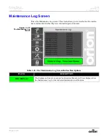
Page 78: ...llows you to look back at the mainte nance alarms and whether they were Acknowledged or Snoozed Figure 3 32 The Maintenance Log Screen Table 3 31 The Maintenance Log Screen Button Descriptions STATE 1...

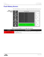
Page 79: ...This is the Fault History screen The screen displays the faults and the time they occurred Figure 3 33 The Fault History Screen Table 3 32 The Fault History Screen Button Descriptions STATE 1 DESCRIPT...

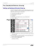
Page 80: ...sed for your flex machine 1 Press Login to log into Admin level security 2 Enter the user password Press Enter 3 Press Diagnostics 4 Press HMI 5 Enter the IP network settings approved by your system a...

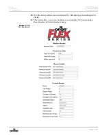
Page 81: ...6 System Operation Page 3 47 10 Once the correct address is entered followed by dashboard asp the dashboard will display 11 This screen allows you to view the Status of your machine the Production dat...

Page 82: ...ION CORRECTION MACHINE SETUP REQUIRED SELECT MACHINE OPTIONS The machine setup parameters are not set See Machine Setup Screen on page 3 26 APPLYING TOP WRAPS The machine is currently applying the top...

Page 83: ...informational pur poses only No correction neces sary CARRIAGE OBSTACLEDETECTED CLEAR PRESS RESET The obstacle detection is tripped See Carriage Obstacle Detect Error Recovery on page 3 2 READY TO WRA...

Page 84: ...ult con dition once the cause is cor rected CARRIAGE MOVING UP TOO SLOWLY The carriage is moving upward too slowly Check for the cause of the car riage not moving correctly Check the belt drive behind...

Page 85: ...on fault press and release the E stop button to clear the fault Contact Orion Packaging if problem persists RS485 COMMUNICATION FAULT PRESS E STOP TO CLEAR FAULT There is an RS485 communication fault...

Page 86: ...h Re latch and restart when ready END OF ROLL OR BROKEN FILM The film has broken or the roll ran out Re load a new roll if out If bro ken monitor the film Replace roll if problem persists See trou ble...

Page 87: ...splay in the electrical cabinet See VFD manual for fault code information MAIN DRIVE VFD NOT READY CARRIAGE VFD NOT READY X2X COMMUNICATION ERROR There is an X2X communication fault press and release...

Page 88: ...Machine Manual Orion Flex Stretchwrapper Revision 3 0 System Operation 15 February 2016 Page 3 54...

Page 89: ...Orion Machine Manual Revision 3 0 Flex Stretchwrapper 15 February 2016 Troubleshooting Contents Page I Troubleshooting Contents Troubleshooting 4 1...

Page 90: ...Machine Manual Orion Flex Stretchwrapper Revision 3 0 Troubleshooting Contents 15 February 2016 Page II...

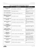
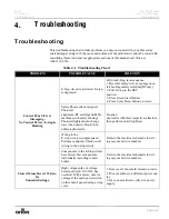
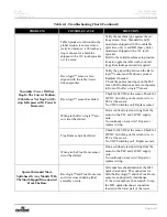
Page 91: ...button on screen Safety Photocells not aligned Photocell alignment RT models and Table machines with safety fencing Photocell lights should change state when objects block then unblock photocells Re a...

Page 92: ...wer preset speeds are set incorrectly The table turnta ble is overhauling and the drive can not stop the load fast enough Check the value of the SP 2 SP 3 and SP 4 parameters on the Table Tower VFD En...

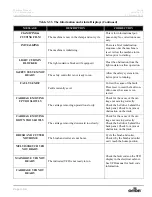
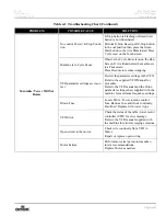
Page 93: ...evo logic sensor has failed Check for 24VDC at the sensor Check for 24VDC Switching on the return wire to PLC at the sensor No VDC Switching out Replace sensor Wiring in the Revo logic sen sor circuit...

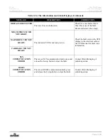
Page 94: ...tage is too low Check AC voltage at the On Off switch terminals while the machine is running under load If voltage drops below 115 the supply is not strong enough to run the machine cor rectly Contact...

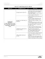
Page 95: ...incor rect Review the parameter settings in the VFD Refer to the supplied VFD Manual for procedure Refer to the VFD manual and the Orion parameter settings sheet supplied with the machine for maximum...

Page 96: ...requirement position within the machine s capability or a jam may occur 2 Position the Bottom travel striker to the lowest wrapping requirement level within the machine s capability or a false Belt Er...

Page 97: ...rrectly aligned belt or carriage safety cam locks Identify and repair or replace worn parts Maximum speed setting on the VFD is incorrect Review the maximum frequency parame ter settings in the VFD Re...

Page 98: ...ll Not Move Up Or Down In Auto Wrap Cycle Only but Works Fine In Manual Mode Auto height photocell positioned incorrectly Check the position of the Auto height photocell Make sure it is aimed at the l...

Page 99: ...switch activates it s PLC input before the carriage physically hits the machine s framework The belt will need to be removed and re wound cor rectly The carriage will need to be brought down manually...

Page 100: ...bar cam is positioned incorrectly Make sure the cam rotates in such a way as to create a gap between the hall effect device and the cam itself Adjust the cam correctly hall effect sensor has failed C...

Page 101: ...e hall effect device and the cam itself Adjust the cam correctly Hall effect device has failed Perform tests mentioned above If this does not resolve the issue replace the hall effect device Minimum s...

Page 102: ...cor rectly on the trailing rubber roller Film mandrel drag or resistance is not allowing the film to unwind properly Look for excessive wear under the bottom mandrel Lubricate the bottom and center o...

Page 103: ...touchscreen Re set the ZERO and GAIN values according to the film feed setup instruc tions in the manual ZERO setting should be a value of at least ten above the hall effect feedback value to operate...

Page 104: ...g the feed axis of the film This is known as gauge banding Replace improper film with film in good condition Stretch chain and or belt geome try is incorrect Out of alignment components can cause feed...

Page 105: ...the flow controls on the clamp cylinders so that they operate smoothly Air lines are pinched or obstructed observe all 1 4 inch polyflow tubing Remove any obstruction Correct any pinched lines Debris...

Page 106: ...e cutter jog function on the touchscreen Adjust the flow controls on the clamp cylinders so that they operate smoothly Air lines are pinched or obstructed observe all 1 4 inch polyflow tubing Remove a...

Page 107: ...h extend timer at the touch screen is incorrect for the applica tion Look for the arm to activate smoothly but at the wrong time Observe the factory preset value on the settings screen Re adjust the b...

Page 108: ...Machine Manual Orion Flex Stretchwrapper Revision 3 0 Troubleshooting 15 February 2016 Page 4 18...

Page 109: ...nce 5 1 Motor Maintenance 5 1 Reducer Oil Change 5 1 Tower Raceways Maintenance 5 2 Chain Maintenance 5 2 Proximity Sensor Adjustment 5 3 Cleaning The Stretch Rollers 5 5 Preventative Maintenance Sche...

Page 110: ...Machine Manual Orion Flex Stretchwrapper Revision 3 0 Maintenance Contents 15 February 2016 Page II...

Page 111: ...ked for tightness after the first week It is recommended to change the oil every six months or at least 1800 hours of operation whichever comes first When adding or changing oil the transmission shoul...

Page 112: ...rosive environment the race ways should be re greased more often at least every 100 hours Chain Maintenance To clean the stretch chain wipe it with an oily cloth once a service quarter When machine is...

Page 113: ...n the cam and the front side of proximity sensor about 1 8 5 Tighten on the nuts securing the Proximity Sensor 6 Put the cover back on 7 Power up machine 8 To adjust the multistretch settings you must...

Page 114: ...Machine Manual Orion Flex Stretchwrapper Revision 3 0 Maintenance 15 February 2016 Page 5 4 14 If not satisfied repeat the procedure Figure 5 2 Proximity Sensor Adjustment...

Page 115: ...pletely normal under continued use and occurs on every stretch wrapper made no matter who the manufacturer is The rubber rollers are recommended to be cleaned at every 2000 hours of running Do not cle...

Page 116: ...ents of actual use and conditions All H L Standard Series 5 760 Loads or one month Inspect rubber stretch rollers Clean as needed per instructions in manual Inspect belt condition Adjust as needed 17...

Page 117: ...ectly on the ring bearing Pump one full shot of grease into the zerk every six months This should be plenty of lubrication for most applications Pumping too much grease into the ring bearing can destr...

Page 118: ...t casters for good condition Inspect turntable chain Apply a light coating of lubricant per instructions in manual Inspect prestretch chain and belt Tension as needed Apply a light coating of lubrican...

Page 119: ...icate per instructions in manual Inspect commutator assembly Blow out debris per instructions in the manual RTA Series 5760 Loads or one month Inspect rubber stretch rollers Clean as needed per instru...

Page 120: ...Machine Manual Orion Flex Stretchwrapper Revision 3 0 Maintenance 15 February 2016 Page 5 10...

Page 121: ...n Machine Manual Revision 3 0 Flex Stretchwrapper 15 February 2016 Electrical Prints and Mechanical Drawings Page 1 Electrical Prints and Mechanical Drawings Electrical Prints 6 1 Mechanical Drawings...

Page 122: ...Machine Manual Orion Flex Stretchwrapper Revision 3 0 Electrical Prints and Mechanical Drawings 15 February 2016 Page 2...

Page 123: ...6 Page 6 1 Orion Machine Manual Revision 3 0 Flex Stretchwrapper 15 February 2016 Electrical Prints and Mechanical Drawings Electrical Prints and Mechanical Drawings Electrical Prints...

Page 124: ......

Page 125: ......

Page 126: ......

Page 127: ......

Page 128: ......

Page 129: ......

Page 130: ......

Page 131: ......

Page 132: ......

Page 133: ......

Page 134: ...G R...

Page 135: ......

Page 136: ......

Page 137: ......

Page 138: ......

Page 139: ......

Page 140: ......

Page 141: ......

Page 142: ......

Page 143: ......

Page 144: ......

Page 145: ......

Page 146: ......

Page 147: ......

Page 148: ...G R...

Page 149: ......

Page 150: ......

Page 151: ......

Page 152: ......

Page 153: ......

Page 154: ......

Page 155: ......

Page 156: ......

Page 157: ......

Page 158: ......

Page 159: ......

Page 160: ......

Page 161: ......

Page 162: ...G R...

Page 163: ......

Page 164: ......

Page 165: ......

Page 166: ...r Revision 3 0 Electrical Prints and Mechanical Drawings 15 February 2016 Page 6 2 Mechanical Drawings Download the mechanical drawings for your particular model on the Orion Webpage http www orionpac...

Reviews: