Orion 9791 Instruction Manual Download Page 26

26

eyepieces. A wider field can be desirable for viewing extended 
deep-sky objects that are too large to fit within a narrower 
field of view.

Tube Balance

With the three counterweights installed on the back of the 
rear cell, the XX14i optical tube will achieve proper balance 
with its supplied accessories. For heavier front-end loads, 
such as if you use a larger finder scope or a heavier eyepiece, 
the CorrecTension system of the XX14i can be adjusted to 
compensate for the added weight, to maintain good tube bal-
ance. Simply tighten the altitude tensioning knob on the left 
side of the base as needed to keep the front of the tube from 
spontaneously drifting downward. 

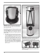
Disassembling the Telescope for Transport 

Despite being a large-aperture instrument, the XX14i has 
been  designed  to  be  easy  to  transport. The  optical  tube 
uncouples from the base, the optical tube disassembles into 
manageable chunks, the base breaks down quickly into four 
main components, and each component can be carried sepa-
rately. 
Before disassembling the telescope, remove the finder scope 
(with bracket) and any eyepieces from the optical tube, and 
remove the IntelliScope Object Locator from the base. The 
eyepiece rack can also be removed from the base, if you wish. 
This will prevent these accessories from being damaged dur-
ing transport. These items can be placed in optional acces-
sory cases.

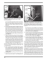
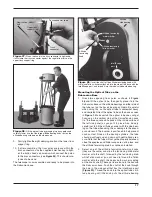
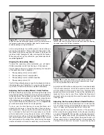
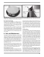
Disassembly of the Optical Tube

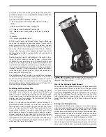
To remove the optical tube from the base, simply unthread the 
altitude tensioning knob and altitude retaining knob from the 
tube’s altitude side bearings until they are free of the tube and 
base. (Be careful to not lose the small spacer on the altitude 
retaining knob shaft; see 

Figure 30

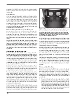
). Then, using both hands, 

carefully lift the tube off the base and set it on the ground. It 
is convenient to lift the tube by grasping opposing truss poles 

(Figure 28).

 The tube is somewhat heavy, so don’t hesitate to 

have a friend help lift it, if necessary.
Note: If you choose to thread the knobs back into the altitude 
bearings  after  removing  the  optical  tube  from  the  base,  be 
careful not to put weight or stress on the knobs when trans-
porting the telescope, or the knob shafts could bend.

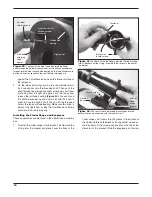
To disassemble the optical tube, unthread the knobs in the 
truss  pole  connectors  from  the  upper  truss  support  ring 
while holding the upper tube section. Once all four knobs are 
unthreaded, remove the upper tube section. Now, unthread 
the eight knobs on the pole ends from the lower truss support 
ring, and remove the truss pole assemblies from the lower 
tube section. Place the dust covers on the tops of the upper 
and lower tube sections. The telescope is now disassembled 
and ready to be transported. 
Note: In step 5 of Assembly of the Optical Tube, it was sug-
gested that the lower tube section could be installed on the 
base before attaching the truss poles and upper tube section. 
Likewise, to avoid having to lift the entire optical tube assem-

bly off the base, you could disassemble the top tube section 
and then remove the truss poles while the lower tube section 
is still mounted on the base. Then, remove the tensioning and 
retaining knobs from the side bearings, grasp the tube by the 
upper end ring with both hands, and lift it off the altitude bear-
ing cylinders and set it on the ground. 

We recommend keeping the counterweights attached to the 
rear cell. But if you wish to remove them for transport – which 
will make the lower tube section about 7 lbs. lighter -- just be 
sure to re-mount them before placing the optical tube on the 
base the next time you reassemble the telescope, or else the 
tube will be out of balance, i.e., front heavy, and could swing 
forward.
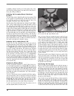
If possible, we recommend transporting the lower optical tube 
section in the upright position, with the mirror parallel to the 
ground. This isn’t absolutely necessary, but doing so will mini-
mize the stress on the mirror’s edge from the retaining bolts 
and retaining washers, especially when going over bumps in 
the road.

Disassembly of the Base

When fully assembled, the XX14i’s base is somewhat bulky. 
But is was cleverly designed to permit quick disassembly into 
smaller components, allowing it to fit into a smaller space – 
in a standard size car trunk or back seat, for instance – for 
transport to a remote observing location. If you choose not 
to disassemble the base, you can carry it with the convenient 
carry handle. 

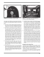
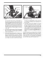
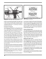
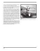
Disconnect the azimuth encoder cable from the azimuth 

1. 

encoder jack in the top baseplate. Then disconnect the 
altitude encoder cable from the altitude encoder jack on 
the right side panel, and remove the cable from the cable 
clip on the right side panel 

(Figure 45).

 If desired, you 

could also completely disconnect both cables by also dis-
connecting them from the encoder connector board and 
from the two cable clips on the left side panel.

Figure 45. 

Before disassembling the base for transport, be sure 

to disconnect the encoder cables from the encoder board jacks and 

from any cable clips on surfaces other than the left side panel. To 

remove the side panel/front panel structure from the top baseplate, 

loosen the eight captive connecting bolts that attach the structure to 

the baseplate. You’ll have to turn each hand knob at least seven full 

turns to completely disengage the bolts. 

Summary of Contents for 9791

Page 1: ...er Support 800 676 1343 E mail support telescope com Corporate Offices 831 763 7000 89 Hangar Way Watsonville CA 95076 Orion SkyQuest XX14i IntelliScope Truss Tube Dobsonian 9791 Providing Exceptional...

Page 2: ...2 Figure 1 The SkyQuest XX14i IntelliScope Truss Tube Dobsonian...

Page 3: ...t use of the telescope 1 Unpacking The telescope is packed in four shipping boxes as detailed below We recommend keeping the original packaging In the event that the telescope needs to be shipped to a...

Page 4: ...yepiece IntelliScope Object Locator Kit Software 9x50 Finder scope Finder scope bracket with O ring Collimation cap Hex keys x3 Washers Cooling fan mounting screws Upper tube section Lower tube sectio...

Page 5: ...r disk 1 Controller cable coil cable 1 Azimuth encoder cable shorter 1 Altitude encoder cable longer 1 Azimuth encoder spacer washer thin 1 4 outer dia 0 015 thick 4 Encoder connector board washers 3...

Page 6: ...10mm long 15mm dia 1 Insertion tube for rubber washers 3 long 3 Counterweight attachment bolts hex head 1 long black 1 Brass azimuth bushing 1 Azimuth axis bolt hex head 2 75 long 2 Fender washers 1 o...

Page 7: ...ical stop knob Fender washers x2 Altitude tensioning metal washer Vertical stop washers 2 thin 2 thick Altitude tensioning Teflon washer Hex lock nut Counterweight mounting bolts x3 Azimuth axis bolt...

Page 8: ...is hefty 14 Dob has the portability and manageability of a smaller telescope Refer to Figure 7 during base assembly When tightening screws tighten them until firm but be careful not to strip the holes...

Page 9: ...9 N R R M B C D L N O H P J E F A H I Q Q G x12 S x12 T x12 Figure 7 Exploded view of the XX14i base...

Page 10: ...liScope Object Locator kit Insert the modular jack on the azimuth encoder board E 8 into the rectangular cutout in the top baseplate D and align the encoder board so the screw lines up with the pre dr...

Page 11: ...les in each side panel The beveled end of the cylinder should be facing away from the side panel Push a bearing cyl inder screw through the side panel and thread it into the built in nut in the cylind...

Page 12: ...able should plug into the jack on the left side of the encoder connector board Figure 14 Connect one end of the altitude encoder cable the longer 20 of the two flat cables in the IntelliScope kit to t...

Page 13: ...d ing or removing one or more of the supplied thick and or thin washers Adjusting the vertical stop is required when using the IntelliScope Object Locator since the optical tube must point precisely v...

Page 14: ...least three full turns of engage ment on the shafts The mirror cell is now almost ready to be installed onto the lower tube section Before doing so check to make sure that the three mir 4 ror retaini...

Page 15: ...tion instructions For the three counterweights thread them onto the counterweight mounting bolts as far as they will go and tighten them lightly against the metal plate Figure 22 Now the upper and low...

Page 16: ...the knobs and holes line up Figure 26 When tightened the knob will clamp the truss connector against the regis tration flats on the upper truss support ring Figure 27 Repeat this for the other three...

Page 17: ...pres sure Note that the tube will not yet be properly balanced since the eyepiece and finder scope are not in place and the altitude tensioning knob has not been installed Select one of the altitude t...

Page 18: ...et and place it over the body of the finder scope until it seats into the groove in the middle of the finder Unthread the black nylon alignment screws on the bracket until the screw ends are flush wit...

Page 19: ...usly Figure 33 The other eyepiece and 1 25 adapter can be placed in the eyepiece rack until they are needed To install the 10mm Sirius Pl ssl eyepiece 1 25 instead 4 of the 2 DeepView eyepiece keep th...

Page 20: ...4i has a small adhesive ring marking its center This center mark allows you to achieve a very precise collimation you don t have to guess where the exact center of the mirror is NOTE The center ring s...

Page 21: ...head screwdriver with your other hand Figure 38 Turning the screw clockwise will move the secondary mirror toward the front opening of the optical tube while turning the screw counter clockwise will...

Page 22: ...the collimation cap is off center The tilt of the primary mirror is adjusted with three spring loaded collimation knobs on the back end of the optical tube bottom of the primary mirror cell these are...

Page 23: ...e the base to tip because of the reduced leverage In this case it is helpful to place your other hand on the base or the optical tube to help guide the tube Setting the Altitude Tension A nice feature...

Page 24: ...he weight of the eyepiece you can adjust it by tightening or loosening the drawtube ten sioning set screw on the focuser which is located just below the focus lock thumb screw Figure 33 Adjust this se...

Page 25: ...e finder scope If your general aim is accu rate the object should appear somewhere in the field of view Make small adjustments to the telescope s position until the object is centered on the finder s...

Page 26: ...lower tube section Place the dust covers on the tops of the upper and lower tube sections The telescope is now disassembled and ready to be transported Note In step 5 of Assembly of the Optical Tube...

Page 27: ...onomical Observing The SkyQuest XX14i IntelliScope Truss Tube Dobsonian pro vides prodigious capability for observing the many wonders of the heavens from the major planets to deep space nebulas and g...

Page 28: ...Moon are bright enough to see clearly even from light polluted city skies for nebulas galaxies and most star clusters the less ambient light there is to reduce contrast the better When it isn t possi...

Page 29: ...an off by unplugging the battery pack Let Your Eyes Dark Adapt Do not expect to go from a lighted house into the darkness of the outdoors at night and immediately see faint nebulas galaxies and star c...

Page 30: ...subject for observation You can see the disk of the giant planet and watch the ever changing positions of its four largest moons Io Callisto Europa and Ganymede Higher power eyepieces should bring out...

Page 31: ...rcular motion then remove any excess fluid with a fresh lens tissue Oily fingerprints and smudges may be removed using this method Use caution rubbing too hard may scratch the lens For larger lenses c...

Page 32: ...across the mirror Then rinse the mir ror under a stream of lukewarm water Any particles on the surface can be swabbed gently with a series of cotton balls each used just one time Dry the mirror in a...

Page 33: ...ower tube section 52 9 lbs Upper tube section 9 4 lbs Truss pole assemblies 6 9 lbs OTA length assembled 61 OTA length disassembled Lower tube section 21 75 long Upper tube section 8 1 long Truss pole...

Page 34: ...turned postage paid to Orion Warranty Repair 89 Hangar Way Watsonville CA 95076 Proof of purchase such as a copy of the original receipt is required This warranty does not apply if in Orion s judgment...

Reviews: