


13
from its jack on the altitude encoder board and from the clip
at the bottom of the right side panel. Both cables could be left
connected to the encoder connector board on the left side
panel.
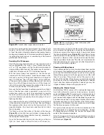
Insert one end of the controller coil cable into the larger of
22.
the two jacks on the top of the IntelliScope Object Locator.
Insert the other end into the “IntelliScope Computerized
Controller Port” in the left panel of the Dobsonian base.
Two hook-and-loop strips (one strip of “hooks” and
23.
one strip of “loops”) have been provided to hang the
IntelliScope Object Locator in a convenient location on
the base when not in use. Place the “hooks” strip on the
back of the controller, and the “loops” strip on the base in
a convenient spot. Make certain the location of the strip
on the base will not cause the Object Locator to inter-
fere with the motions of the telescope. We recommend
the placement shown in
Figure 1.
You may want to con-
sider using the optional holster instead of the supplied
hook-and-loop strips. The holster is a metal holder cus-
tom designed to fit the IntelliScope Object Locator. When
installed at the top of the Dobsonian base, it provides a
firm mounting for the Object Locator at a convenient posi-
tion for easy access. The Object Locator can be removed
or kept in the holster during use.
Slide the battery cover off the back of the Object Locator
24.
and insert the 9-volt alkaline battery. Make sure the posi-
tive and negative terminals of the battery are oriented as
shown in the bottom of the battery compartment. Replace
the battery cover.
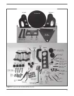
Attach the handle (M in Figure 7) to the front brace (B)
25.
with the two handle screws. Place one handle washer on
each screw, then press the handle against the front brace
(the end of the handle with the Orion logo should be fac-
ing upwards). Thread the screws from the interior surface
of the front brace into the handle until tight using the sup-
plied crescent wrench.
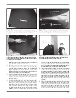
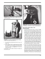
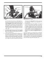
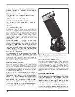
Thread the vertical stop knob into the threaded insert on
26.
the inside of the front brace (B) until just tight
(Figure
17).
The position of the vertical stop is adjusted by add-
ing or removing one or more of the supplied thick and/
or thin washers. Adjusting the vertical stop is required
when using the IntelliScope Object Locator, since the
optical tube must point precisely vertical during the ini-
tial alignment procedure. The manual included with the
IntelliScope Object Locator kit details the procedure for
adjusting the vertical stop. Once the vertical stop is prop-
erly adjusted, it should not need to be adjusted again for
subsequent observing sessions.
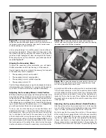
The aluminum eyepiece rack holds three 1.25" eyepieces
27.
and one 2" eyepiece in a convenient place on the base,
within easy reach while you’re observing. Above the oval
cutout in the left side panel you will notice two pilot holes
located approximately 6" apart. Thread the eyepiece rack
screws into the holes with a Phillips screwdriver until the
screw heads are about 1/8" from being flush with the
side panel. Place the large portion of the eyepiece rack’s
“keyhole” mounting slots over the two screw heads, then
slide the rack downward. If you want to be able to remove
the rack for transport or storage of the telescope, be sure
the screws are loose enough so you can lift the rack and
remove it from the base through the large opening of the
“keyhole.” If you wish to permanently attach the rack to
the base, tighten the two screws until the rack is secured
in place.
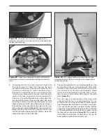
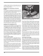
assembly of the Optical Tube
The primary mirror is shipped in its cell separately from the
optical tube, to prevent possible damage to both the mirror
and the optical tube. Once the primary mirror is installed in the
telescope, there will be no need to remove the mirror, except
if cleaning is necessary (see “Cleaning Mirrors”).
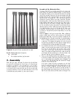
First, the mirror will be installed into the tube, then, the upper
and lower sections of the tube will be assembled together with
the truss poles.
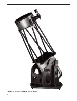
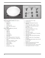
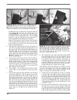
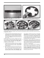
Figure 16.
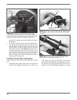
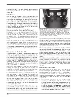
Install the bumper into the pilot hole above the altitude
encoder assembly using one of the encoder wood screws.
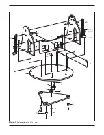
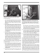
Figure 17.
Recommended cable routing and cable clip
placement. If you don’t intend to disassemble the base routinely for
transport, you could use additional cable clips.
Altitude
encoder
assembly
Altitude
encoder cable
Vertical stop knob
Azimuth encoder cable
Cable clips
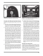
Bumper
Encoder
wood
screw
Encoder connector board
Altitude encoder board assembly