
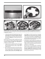


12
to do, but by lightly pressing the screw tips into the holes,
they should “stick” enough so that you can screw them in
without one or more of them (and the washers) falling out.
Using a small Phillips screwdriver, tighten all four screws
(Figure 14).
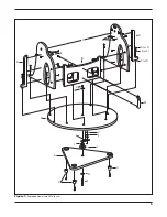
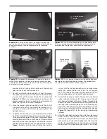
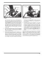
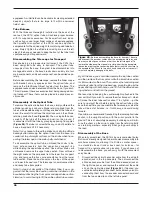
The altitude encoder assembly is installed onto the base’s
16.
right side panel. Below the 5/8" through hole in the right
panel, there are two predrilled starter holes in the inward-
facing surface. Take two of the encoder wood screws sup-
plied in the IntelliScope kit and push them through the
two slotted holes in the bottom of the altitude encoder
board. The screw heads should be on the same side as
the altitude encoder’s modular jack. Now, place an alti-
tude encoder nylon spacer washer on the end of each
screw
(Figure 15).
Thread the encoder wood screws into the starter holes
17.
in the right side panel with a Phillips screwdriver
(Figure
15).
The shaft on the altitude encoder assembly should
protrude through the 5/8" through-hole in the right panel.
It will take a bit of dexterity to keep the nylon spacer
washers on the ends of the screws when installing, so
don’t get frustrated if it takes a couple tries. The screws
should not be fully tightened; they should be tight, but not
tight enough to prevent the altitude encoder from moving
up and down within the slots in the encoder board.
Note: The right panel does not have a white nylon bushing
pressed into its 5/8" through hole like the left panel does. This
is an intended design.
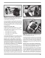
There is a pilot hole above the altitude encoder assembly;
18.
this is where the plastic bumper (found in the IntelliScope
kit) that protects the altitude encoder assembly will be
installed. Take the remaining encoder wood screw from
the IntelliScope kit, push it through the bumper, and use
a Phillips screwdriver to thread it into the pilot hole until
tight
(Figure 16).
Connect one end of the azimuth encoder cable (the
19.
shorter of the two flat cables in the IntelliScope kit) to
the encoder jack in the top baseplate of the Dobsonian
base. Connect the other end to the encoder connector
board installed on the base’s left side panel. The azimuth
encoder cable should plug into the jack on the left side of
the encoder connector board
(Figure 14).
Connect one end of the altitude encoder cable (the longer
20.
of the two flat cables in the IntelliScope kit) to the modular
jack on the altitude encoder assembly. Connect the other
end of the altitude encoder cable to the jack on the right
side of the encoder connector board
(Figure 14).
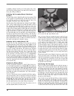
Use the cable clips provided with the IntelliScope kit to
21.
secure the altitude and azimuth cables neatly to the base.
The clips have adhesive backing; simply peel the paper
off the back of the clip and press the adhesive back to the
base where you want the clip to be located.
Note: Plan your placement of the clips carefully! If you intend
to disassemble the side and front panels of the base for trans-
port or storage, you should first disconnect the encoder cables
from one or both of their respective jacks. And you will have
to remove the cables from any cable clips on base surfaces
where the cable is not plugged into a jack. So we recommend
using as few cable clips as possible to make things easy dur-
ing disassembly and re-assembly of the base.
See
Figure 17
for recommended cable and cable clip place-
ment. In that arrangement, only one clip is used to secure the
(shorter) azimuth cable and two clips to secure the (longer)
altitude cable. All three clips are affixed to the side panels.
Before disassembling the side and front panels (we don’t rec-
ommend disassembling the top baseplate from the ground
baseplate), you would disconnect the azimuth cable from its
jack in the top baseplate, and disconnect the altitude cable
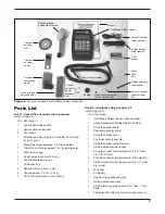
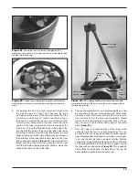
Figure 15.
To install the altitude encoder assembly onto the
interior surface of the right side panel, insert two encoder wood
screws through the slotted holes in the board. Then, add an altitude
encoder nylon spacer washer onto each screw. Now, insert the
shaft of the altitude encoder through the hole in the right side panel,
and thread the screws into the two pilot holes using a Phillips head
screwdriver.
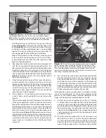
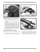
Figure 14.
Attach the encoder connector board to the left side
panel with four of the encoder wood screws and four encoder
connector board washers.
Altitude
encoder
jack
Azimuth encoder jack
Encoder wood
screws (4x)
Left
panel
Altitude encoder
nylon spacer
washer
Encoder
mounting screw
Altitude
encoder
assembly
Right panel