background image

28

29

Color images from CCD cameras typically require a background level adjust-
ment. This is accomplished by bringing the background level (or bias) in each 
color plane down to zero. Each of the 

Background Level

 values is subtracted 

from every image pixel in its color plane. Any pixel values that become nega-
tive are forced to zero. The 

Auto

 button automatically determines the settings 

necessary  to  equalize  the  image  background  in  all  three  color  planes.  The 

Reset

 button resets the background level subtraction to zero on all planes. 

Scaling

 adjustment (entered as a percentage) allows you to compensate for 

transmittance differences between the filters used to acquire the three color 
planes. Values of 100% result in no change. The scaling percentages can be 
typed in or adjusted using the “spin” controls (small up and down click arrows 
to the right of the scaling numbers). The 

Preview Image

 is particularly help-

ful in monitoring the results when using the spin controls. The 

Reset Scaling


button resets to 100% on all three planes.
The 

Click On White Area to Set Scaling

 check box enables the operation 

of the mouse to set the scaling. Set the 

Background Level

 first (you can use 

Auto

), then click on a white object (e.g. a neutral-colored star) in the image (not 

the 

Preview Image

) with the mouse. The 

Scaling

 settings will automatically 

be adjusted to make the selected point appear white. If an area of the image 

is known to be white (or gray), this is an easier way to determine the scaling 
factors, and can be used to instantly color balance the image.

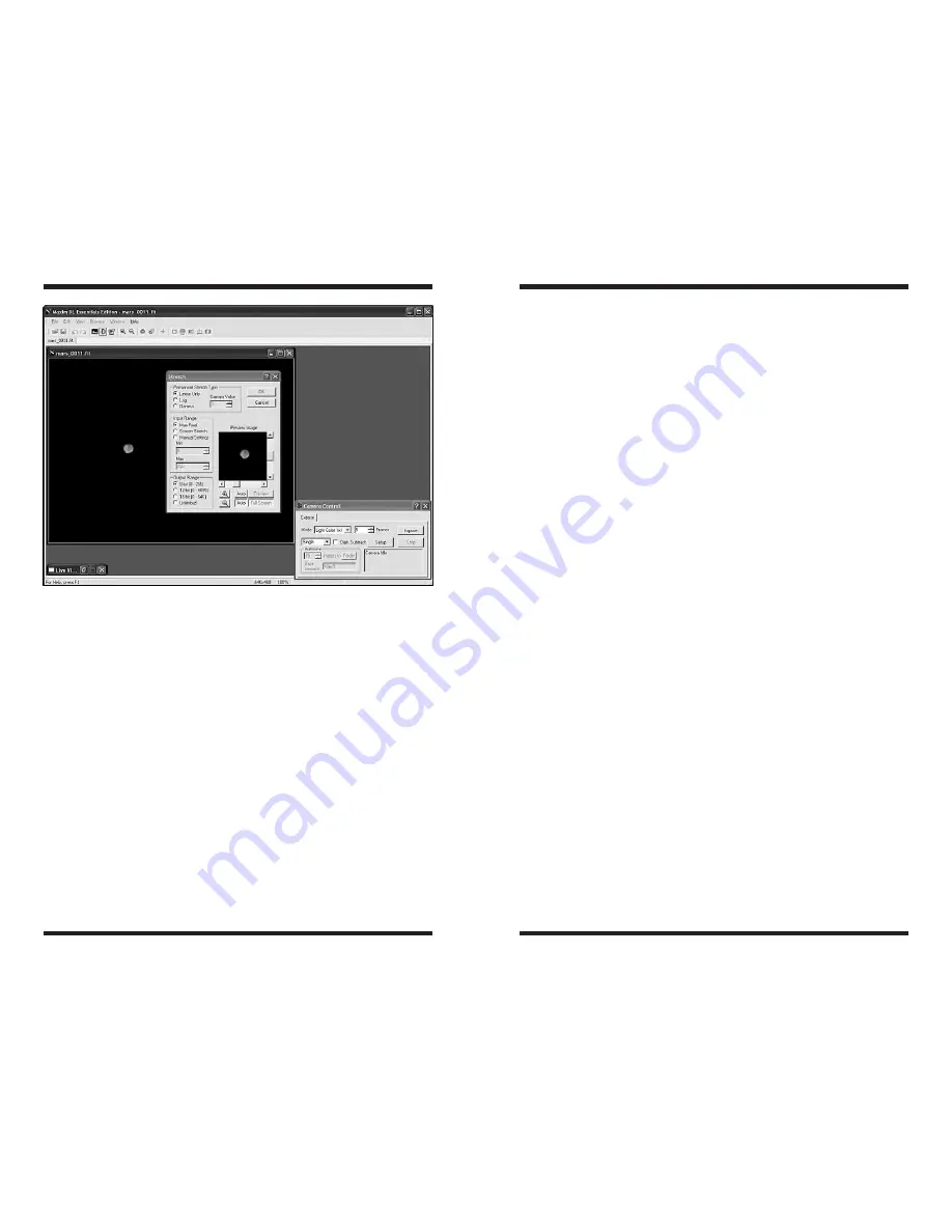
Stretch

The 

Stretch

 command (located in the 

Process

 menu, Figure 21) modifies the 

brightness  and  contrast,  and  optionally  the  range  (maximum  and  minimum 
pixel  values)  of  an  image.  Unlike  the  screen  stretch  settings  in  the 

Screen 

Stretch Window

, which only affects the how an image appears on the com-

puter  screen,  the 

Stretch

  command  actually  changes  the  image  data  pixel 

values in the memory buffer. In reference to the histogram, the 

Screen Stretch 

Window

 changes how the histogram is displayed on the computer screen, the 

Stretch

 command alters the histogram itself.

There are three elements which must be set: the 

Permanent Stretch Type

the 

Input Range

, and the 

Output Range

. You can use the 

Preview Image

 to 

see how changing these parameters will affect the resultant image (or click the 

Full Screen

 button to see the changes applied to your actual image). You can 

also  open  the 

Screen  Stretch  Window

  to  see  how  changing  these  param-

eters change the histogram.
For the 

Permanent Stretch Type

, the 

Linear Only

 mode is useful for adjust-

ing the range of pixels to match a particular file format. The 

Log

 mode is useful 

for compressing the dynamic range of the image, but can be rather harsh. The 

Gamma

 mode allows you to selectively emphasize bright or dim parts of the 

image by entering a suitable 

Gamma Value

. A 

Gamma

 of 1 has no effect, less 

than 1 will emphasize faint details, while a value greater than 1 will emphasize 
bright details.
The 

Input Range

 can be set to 

Screen Stretch

, which in 

Linear Mode

 pro-

duces  an  output  matching  the  current  screen  appearance.  This  is  useful  in 
producing final images for output to 8-bit image formats which have limited 
range. Note that the minimum and maximum values are always taken from the 
screen stretch settings for the original image. These can be adjusted dynami-
cally  using,  for  example, 

Quick  Stretch

.  The 

Max  Pixel

  selection  sets  the 

input range from 0 to the brightest pixel in the image. This prevents any image 
pixels from being saturated in the final result, but may produce images with 
low  contrast.  You  can  also  manually  set  values  with 

Manual  Settings

  in  a 

similar fashion to the Screen 

Stretch Window

.

The 

Output Range

 is used when preparing a file to be saved in a format that 

has limited range. The 

Output Range

 maps minimum input to zero, and maxi-

mum input to 255, 4095, or 65535 depending on the settings. Any values that 
exceed the limits are clipped. The Unlimited setting disables all limiting and is 
recommended when performing 

Gamma

 and 

Log

 stretches; it is appropriate 

when the image will be saved in floating point format.

Figure 21. 

The 

Stretch 

command modifies the data contained within the image in 

order to improve contrast and brightness.

Summary of Contents for 52085

Page 1: ...52085 instruction Manual Providing Exceptional Consumer Optical Products Since 1975 Customer Support 800 676 1343 E mail support telescope com OrionTelescopes com Corporate Offices 831 763 7000 89 Ha...

Page 2: ...star clusters and nebulae as well as the planets Moon and the Sun with an optional solar filter You can showcase spectacular images on your computer share them on the internet or print them The camera...

Page 3: ...d the telescope s focal plane to the camera s imaging plane Some telescopes such as refractors may require the use of an extension tube avail able from Orion to provide enough outward focus for the St...

Page 4: ...DC 12VDC with approximately 1 ampere of current Power to the entire camera including the thermo electric cooler TEC and fan is supplied by the included power cable when plugged into a 12VDC power sour...

Page 5: ...cation Advanced and click Next 6 Select Search removable media floppy CD ROM Turn off the other options Click Next Windows will start looking for the driver files on the CD ROM 7 Windows will note tha...

Page 6: ...th tape Figure 7 Obtaining First Images To obtain first images in daylight with the StarShoot Pro follow these step by step instructions 1 With an eyepiece inserted in the telescope center and focus o...

Page 7: ...esented as a number from 1 to 65535 depending on brightness This has to be mapped into the video monitor s brightness range from 1 to 255 It is important to set the screen stretch appropriately or a g...

Page 8: ...h the 12VDC power source The cooler can be shut off if needed for troubleshooting purposes or to save power The cooling fan speed can also be adjusted The TEC is like a refrigerator in the camera When...

Page 9: ...he camera If the Max Pixel approaches 65535 reduce the exposure time or try selecting a fainter star Paying attention to these values will help you get a very accurate focus far better than simply loo...

Page 10: ...ures of 30 Seconds to start 7 Click Expose and the camera will commence taking the images Note When the camera is taking long exposure images it is critically important not to touch shake or otherwise...

Page 11: ...focused and ready for astro imaging 2 Point the telescope at a uniform and featureless light source like the sky at dusk or dawn or a blank white sheet of paper Make sure the camera orientation is ex...

Page 12: ...k frames AFTER the light frame is taken you ensure keeping your raw astro images in tact 5 Select Calibrate from the Process menu or click the Calibrate icon in MaxIm DL Essentials and the dark frames...

Page 13: ...ind a well shaped circular star in the first image displayed Use the mouse to center the crosshairs on the selected star and left click Note In addition to Average men tioned above 3 other different c...

Page 14: ...ation that emphasizes certain characteristics of an image while suppressing others MaxIm DL Essentials supports two kinds of filters Unsharp Mask and Gaussian Blur In the Filter window select which on...

Page 15: ...ram is displayed on the computer screen the Stretch command alters the histogram itself There are three elements which must be set the Permanent Stretch Type the Input Range and the Output Range You c...

Page 16: ...e loss of data especially when saving combined images Batch Process Batch Process can be used to process multiple images simul taneously using the various com mands available in MaxIm DL Essentials Ed...

Page 17: ...l guiding corrections are needed during long expo sure imaging Keep in mind however that when the StarShoot Pro is used in this way you will need another telescope and camera on the mount to actually...

Page 18: ...2 Set the X and Y Aggr aggressiveness to 8 to start with Set the Exposure to 1 0 second Under Guide Star make sure the Watch box is checked Note The X and Y Aggr aggressiveness controls on the Guide t...

Page 19: ...window that pushes the star in that direction That will prevent the stiction cycle from happening Make sure that any backlash compensation in the mount is turned off On most telescopes the Right Ascen...

Page 20: ...time they were minimized This can be handy for sorting images For example when inspecting a set of images you can close the ones you want to reject and minimize the ones you want to keep Once all the...

Page 21: ...ing to change image scale Focal reducers serve to decrease the focal length of your telescope This increases the field of view seen by the camera decreases camera magnifi cation This can be very usefu...

Page 22: ...ncouraged to try to correct the interference by one or more of the following measures Reorient or relocate the receiving antenna Increase the separation between the equipment and receiver Connect the...

Page 23: ...a coming from the camera To re establish camera connection first close the Maxim DL Essentials program on your computer Then unplug and re plug the camera into the computer s USB port Open Maxim DL Es...

Page 24: ...cope focal lengths and their corresponding fields of view provided by the StarShoot Pro The angular field of view is shown in arc minutes The image scale shows the relative size of two reference objec...

Page 25: ...49 Telescope Focal Length Angular Field of View Image Scale of the Moon Image Scale of M42 1000mm 83 3 X 54 4 1250mm 66 6 X 43 5 1800mm 46 3 X 30 2 2032mm 41 X 26 8 2540mm 32 8 X 21 4 2800mm 29 7 X 19...

Page 26: ...r Camera Control Window Subframe Reset 2 A cquire and center the deep sky object you want to image Autosave as many images as you would like 5 or more images is recommended to later combine Take some...

Page 27: ...mage Processing 1 Calibrate darks and flats Select your darks and flats Process Setup Calibrate Add your dark frames flat fields and dark frames for flat fields OK Now calibrate your astro images File...

Page 28: ...________ ________________________________________________________________ ________________________________________________________________ _____________________________________________________________...

Page 29: ...onville CA 95076 If the product is not registered proof of purchase such as a copy of the original invoice is required This warranty does not apply if in Orion s judgment the instrument has been abuse...

Reviews: