


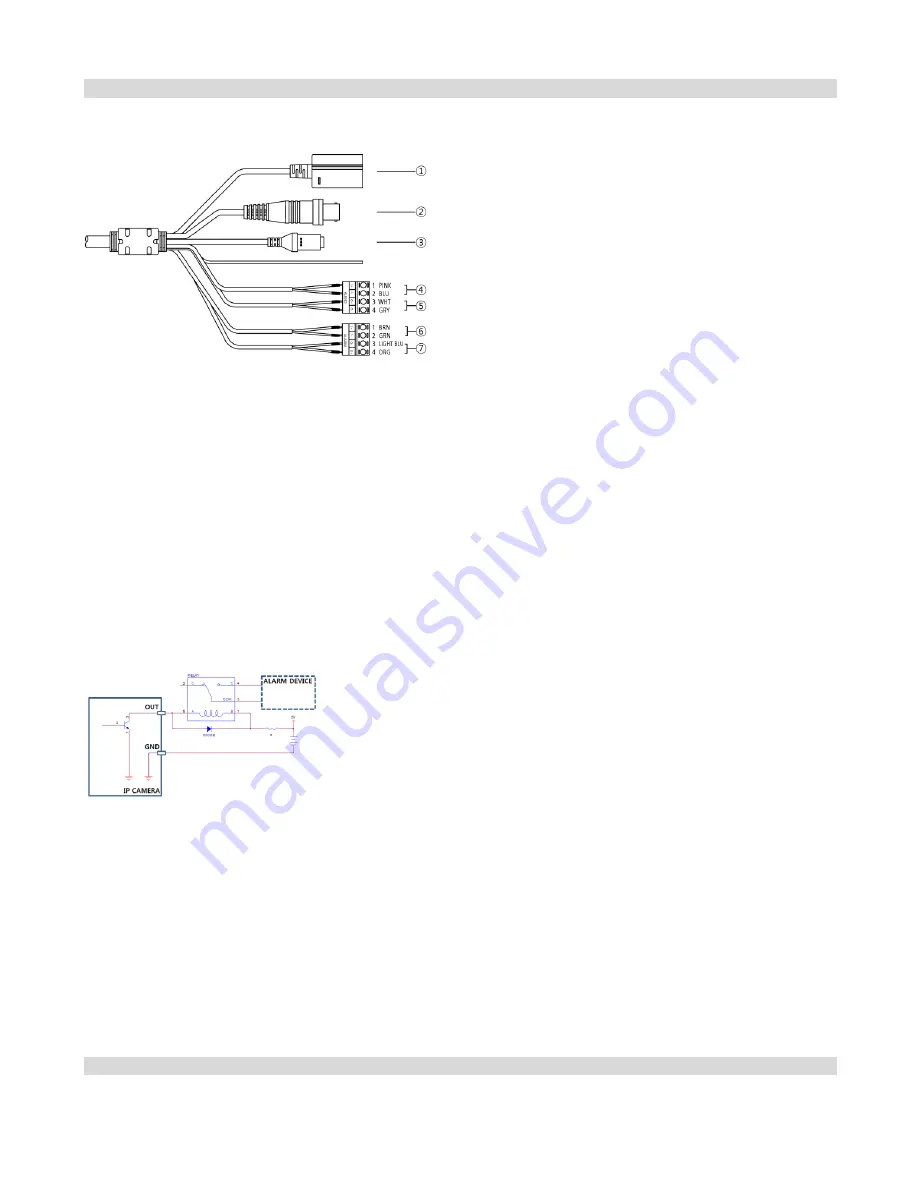
Cable Assembly
①
Network Port
②
BNC Video Out
(yellow cable)
③
Power In
(red cable)
④
Audio In
⑤
Audio Out
⑥
Alarm In
⑦
Alarm Out
Audio Out (black cable): Connect to an amplifier (Line-out). The camera does not have amplified audio output, so you
will need a speaker with an amplifier.
Audio In (white cable): Connect to an audio source (Line-in).
BNC Video Out (yellow cable): Connect to a monitor. This is intended for video preview while adjusting the camera.
Power In (red cable): Connect to the power adapter (12 VDC).
Network Port: Connect a Cat5 cable with an RJ-45 connector. You can change the settings, manage the camera, upgrade
the software or monitor video remotely via the network connection. Refer to the PRO INIT User’s Manual for details about
network connection setup. When using a PoE switch, the camera can be supplied with power over Ethernet cable (Refer to
the PoE switch manufacturer’s manual for details).
Alarm In: Connect an alarm-in device. Mechanical or electrical switches can be wired to the IN and GND (Ground)
connectors. The voltage range is from 0V to 5V. When the electrical switch is wired, the threshold voltage for NC (Normally
Closed) is above 4.3V and for NO (Normally Open) is below 0.3V, and it should be stable at least 0.5 seconds to be detected.
Alarm Out: It is the BJT (Bipolar Junction Transistor) - open collector output. If the voltage and current exceed the
specification limit (max. load: 50mA, max. voltage: 30VDC), the product could be damaged. When connecting the device
which exceeds the specification limit, refer to the picture (circuit) below.
CAUTION: If used with an external
inductive load (e.g. relay), a diode
must be connected in parallel with the
load for protection. Otherwise, the
product could be damaged.
NOTE:
Camera surveillance may be prohibited by laws that vary by region. Check the laws in your area before using this
product for surveillance purposes.
CAUTIONS:
The camera restarts after the power adaptor is disconnected from the camera when switching the power source from
12 VDC to PoE.
The network connector is not designed to be connected directly with cable or wire intended for outdoor use.
WARNING: ROUTE POWER CORDS SO THAT THEY ARE NOT A TRIPPING HAZARD. MAKE CERTAIN THE POWER CORD WILL
NOT BE PINCHED OR ABRADED BY FURNITURE. DO NOT INSTALL POWER CORDS UNDER RUGS OR CARPET. USE THE
POWER CORD THAT HAS A GROUNDING PIN. IF YOUR POWER OUTLET DOES NOT HAVE A GROUNDING PIN RECEPTACLE,
DO NOT MODIFY THE PLUG. DO NOT OVERLOAD THE CIRCUIT BY PLUGGING TOO MANY DEVICES INTO ONE CIRCUIT.
Factory Reset
This will only be used on the rare occasions that you want to return all the settings to the original factory settings. Refer to
the PRO INIT User’s Manual for details on remote factory resetting.
CAUTION: When performing a Factory Reset, you will lose any settings you have saved.
9
9
Summary of Contents for IC110HF011PT13
Page 1: ...Network Camera Operation Manual...
Page 37: ...Part 3 Specification 36...


