38
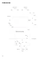
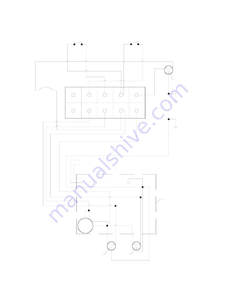
WIRING DIAGRAM
1 (BLK)
WHT
2 (WHT)
1 (BLK)
2 (WHT)
BLK
BLK
BLK
BLU
ORG
BLK
4 (RED)
1 (BLK)
3 (BLU)
2 (WHT)
WHT
WHT
BLK
YLW
Ground
Ground
Ground
Ground
Ground
Ground
Motor
Housing
Wires
Pump Plug
Extra Plug
Motor Wiring Box
SPRAY SWITCH
ON/OFF SWITCH
Circuit Breaker
Power Cord
from Wall
Terminal Strip
inside handle
wiring box
5(YLW) No Connection (Insulated)
6 (BRN) No Connection (Insulated)
Summary of Contents for SPRAYBORG
Page 1: ...OPERATING MANUAL ENG V052015 ...
Page 19: ...19 PARTS ...
Page 21: ...21 PARTS ...
Page 23: ...23 PARTS ...
Page 25: ...25 PARTS 1 2 ...
Page 27: ...27 PARTS ...
Page 29: ...29 PARTS ...
Page 31: ...31 PARTS 13 ...
Page 33: ...33 PARTS 2 1 ...
Page 35: ...35 PARTS ...
Page 37: ...37 PARTS ...
Page 39: ...39 NOTES ...

