2
Connection
Note
Contactors, high power electric motors, frequency drives and other power devices
should not be in a close proximity of the meter. Input signal leads (measured value)
should be seperated from all power lines and power devices. Even though the device
has been designed and tested according to standards for industrial environment, we
strongly advise to adhere to the above presented rules.
1
Description
P
OW
E
R
1
2
3
+ -
4
5
6
+ -
IN
P. 3
10
11
12
7
8
9
+ -
24 V
+
+
+
IN
P. 2
IN
P. 1
10
11
12
7
8
9
10
11
12
7
8
9
-
+
10
11
12
7
8
9
S+
S+
S-
ES+
E+
E+
ES-
E-
ES-
DC, PM
OHM, RTD
DU
T/C
V
+
-
mA
+
-
AO 1
- Voltage
AO 1
- Current, active
AO 1
- Current, passive
mA
+
-
+
1
2
4
5
3
6
7
8
10
11
9
12
SET
SET
PWR
mm
in
mm
in.
8
0.32
mm
2
/ AWG
0.05…2.5 / 30…12
1.5 Nm
13.2 lb-in
Ø 3.5 mm
0.14 in
CONNECTION
TYPE
INPUT U1
INPUT U2
INPUT I
DC
±60 / ±75 / ±100 / ± 150 mV
±300 / ± 1000 mV
±20 / ±40 V
±100 mA
PM
±2 / ±5 / ±10 V
0…5/20 mA, 4…20 mA
OHM
0…0.1 / 0.3 / 1 /3 / 10 / 30/100 / 300 kΩ
Pt
Pt 50 / 100 / 500 / 1000
Cu
Cu 50 / 100
Ni
Ni 1000 / 10000
NTC
NTC 2/2,2/10 / 12 / 20 kΩ
PTC
KTY 81
T/C
J/K/T/E/B/S/ R/N/L
DU
Linear potentiometer, > 500 Ω
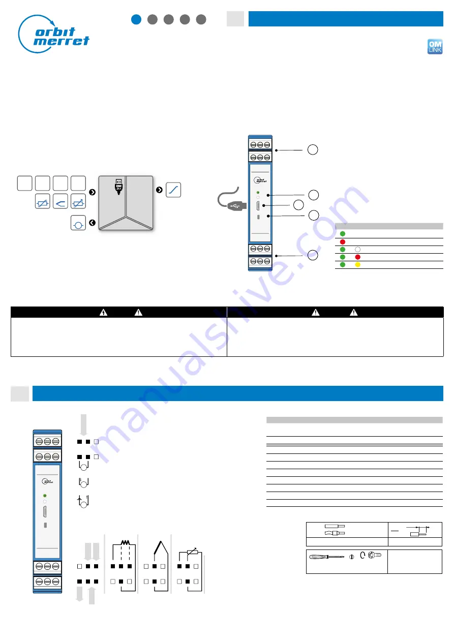
LED INDICATION
PWR
SET
STATUS
Device is running
Device error - processor
Tare function is activated
Sensor error
Simulation mode is activated
MINI-TECHDOK - OMX 311UNI - 2022.1 - en
1 / 4
fr
it
Digital DIN rail mounted signal
convertor
MULTIFUNTION INPUT (DC, PM, RTD, T/C, DU)
z
Multifunction input (DC, PM, RTD, T/C, DU)
z
Configurable type and measuring range
z
Analogue output, passive/active
z
Quick configuration by DIP switch
z
PC configurable via USB port
z
Excitation 24 VDC
z
Galvanic isolation 2.5 kVAC
z
Simple instalation to DIN rail
de
cs
ru
en
fr
Note
There is galvanic connection between USB connector and input!
In case you need to configure the unit while the input signal is connected,
the use of a galvanic isolated OM USB-ISO convertor is recommended..
Legend
① Connectors
② RGB Status LED
③ Control button
④ microUSB port for PC connection
OMX 311UNI
USB
micro
1
1
2
3
4
1
2
4
5
3
6
7
8
10
11
9
12
SET
SET
PWR
DANGER
WARNING
HAZARD OF ELECTRICAL SHOCK
- Disconnect all power and other supply lines before servicing equipment
EQUIPMENT OPERATION HAZARD
- Do not use this product in safety critical system
- Do not disassemble, repair or modify this product
- Do not operate beyond the recommended operating environment
Failure to follow this instruction may result in death or serious injury.
Failure to follow these instructions may result in death, serious injury, or equipment damage.
Electrical equipment should be installed, operated, serviced, and maintained only by qualified personnel.
No responsibility is assumed by ORBIT MERRET for any consequences arising out of the use of this device.
Exc.
-
+
Power
mA
V
IN 1
OUT 1
mA V mV
RTD
Pot.
TC
Ω


