PREPARATION TO WORK
• The machine do not need to be uninstall with the transporting protections.
• It is suggested to store the packaging in case of future transports.
• The machine should be placed on a stable, flat and durable surface.
• Rubber legs protect against surface damages and do not leave marks.
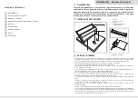
• With the machine there are enclosed:
- Creasing device
- Hexagonal socket wrench 3 mm
CREASING
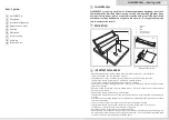
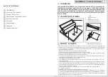
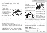
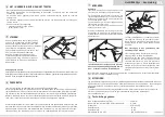
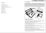
Put the creasing unit on the bar located in
the machine slot and push it down
(see the picture). Distinctive click sound
informs about proper unit installing.
Using front or back gauges set the position
of the crease. Put the material under the bar
and press the arm down.
Changing the creasing bar
Remove the creasing bar from the creasing unit. Take off the strip covering the glued side in the new
bar and place it on a creasing knife using rubber, shaped gauge. Press the bar and remove the rubber
gauge.
PERFORATION
(an additional perforating tool can be purchased along with the device).
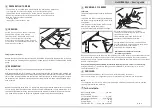
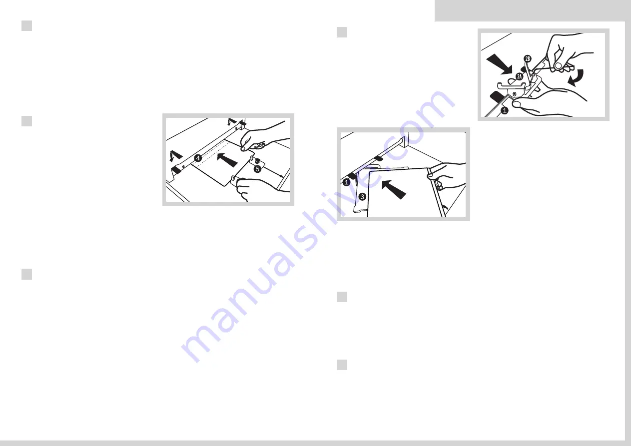
Hold the perforating tool for its handlers, slide it onto the installation bar located in the machine slot
and then push it down (see arrows on the picture nearby). The distinctive click sound confirms that the
tool has been properly installed. Use the front and back limit gauges on the working panel to adjust
the perforation line. Slide the material under the bar and press the arm down until perceptible resist-
ance is sensed.
Behind the perforating knive there is a rubber strip removing perforated material out of the knive.
In case of very intensive utilization the rubber can become deformated, causing deterioration of its
characteristic. Nevertheless during pauze in operation the rubber will recover its shape and character-
istic. A new rubber strip can be purchased together with pads under the perforating knife.
5
4
6
6
MultiCREASE 52 - User’s guide
GB
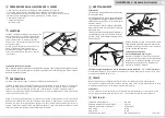
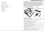
Hold the rounding tool for its handlers,
slide it onto the installation in the machine
slot and align center.
The distinctive click sound confirms that
the tool has been properly installed.
Put the washer (3) under the rounding device.
Put the material to be rounded onto the washer.
Move the material to the limiters
and then press the device lever.
Replacement of the cutter in the tool
for rounding of corners.
Move the limit gauges aside to enable undisturbed access to the cutter. Use the socket wrench 2 mm
to lose the screw located in the front part of the rounding device and push the cutter outside by
depressing on its base. Then reinstall a new cutter and retighten the screw with use of a hex socket
wrench. Lock the cutter.
Due to the sharp edge be extremely careful with handling the tool. There is a risk of injury.
PUNCHING
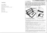
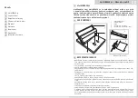
Place the pad under the bar. Put the material, with the cutting blade on it.
Press the arm down. It is suggested to cut it in several phases/ several move of the lever.
Note!
It is suggested to use die-cuts with 19mm blade high offered by the manufacturer to achieve
the best results with the machine
8
9
Technical data:
Max creasing width: ................520 mm
Max thickness
of the creased material: ............0,3 mm
Creasing bar thickness: ........0,7 mm (2Pt)
Net weight: ................................26 kg
Gross weight: ............................29 kg
Size (W x H x D): ......596 x 546 x 265 mm
19.04.11
7
ROUNDING OF CORNERS
Calibration
(It is possible to purchase a rounding tool for this
device).
To position the corner cutter (1) precisely press
the loosen triangular element (2A) to the knife
and tighten.
Then match both side limiters (2B) to the ele-
ment (2A) and tighten them as well.
Use a 3mm hex wrench to tighten the screws.
Using Multicrease 52 is possible to apply all knives offered for O.Corner Cutter, i.e.: O.Corner
Cutter Blade R6, R10, C15
Summary of Contents for multiCREASE 52
Page 19: ...MultiCREASE 52...


