-
26
-
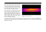
Now a few settings must be made. First, the
scan line must be positioned correctly. Make
sure that the width of the scan line is at least as
wide as the glass that passes through it. This
ensures that the entire glass is scanned.
The scan line can be changed directly in the
lower left window (Line scanner live view). It
can be moved and enlarged or reduced. The
shutter should be open so that the line can be
aligned correctly. Make sure to position the
scan line between the rollers of the conveyor
belt to avoid possible reflections.
Figure 7:
Position of scan line
Furthermore, the "Ext. Ref Sensor G5" measuring area must be moved to the correct position (
). It is
important that the measuring area must be placed at the height of the sensor. The referencing to the IR image
takes place in this area.
Summary of Contents for Top-down GIS
Page 1: ...Operators Manual Top down GIS Glass Inspection System ...
Page 5: ... Table of contents 5 Appendix A Control cabinet 43 ...
Page 11: ... Technical Data 11 Figure 1 Dimensions mm shutter system ...
Page 12: ... 12 Figure 2 Dimensions mm switch cabinet ...
Page 19: ... Technical Data 19 CT G5L SF optics ...
Page 34: ... 34 Figure 16 Linescan in PIX Connect software ...
Page 48: ...Top down GIS MA E2021 07 A ...


