


■ GSC-02A
User's Manual
■
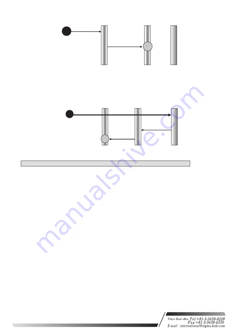
NORM method
Note) If the stage moves in the CW direction and the NEAR sensor can’t detect it (no NEAR
sensor), the stage will stop at the CW sensor.
Note) If the stage moves in the CW direction after detecting the ORG sensor and the ORG sensor
can’t be detected (no ORG sensor), it’ll stop at the CW (CCW) sensor.
MARK method
(21) S command: Switch number of steps (Enabled only for System Type B)
Features:
This command is used to set the number of motor divisions. The default setting is 2.
・Command format
S:nd
・parameter
n: 1 or 2 or W
1: first-axis, 2: second-axis, W: both first-axis and second-axis
d: 1 or 2
1: Full step
2: Half step
(If n is set to W, m needs to be set for two)
Ex1) S:12
Set the number of divisions for first-axis to Half step.
Ex2) S:W21
Set the number of divisions for first-axis to Half step, and set the
number of divisions for second-axis to Full step
Note) During stage operating status is Busy, the command status is NG.
N sensor detection
CW(CCW) sensor
ORG sensor
1/10 ORG SPEED(S)
ORG SPEED(S)
NEAR sensor
O sensor detection
CW sensor
CW LS detection
N sensor detection
O sensor detection
NEAR sensor
CW(−)
ORG SPPED(F)
1/10
ORG SPEED(S)
CCW(+)
ORG SPEED (S)
CCW(+)
ORG sensor
21
Osaka branch
Summary of Contents for GSC-02A
Page 29: ......


