


OPTIMUM
M A S C H I N E N - G E R M A N Y
Version 1.0.1 2014-05-16
Page 128
Original operating instructions
TU2506 | TU2506V | TU2807 | TU2807V
GB
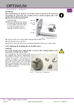
3.22
Terms for the rotating tool
In most cases the setting angle is depending on the work piece. A setting angle of 45° to 75° is
suitable for roughing. setting angle of 90° to 95° (no tendency to chattering) is suitable for plan-
ing.
The corner angle serves as passing from the major cutting edge to the minor cutting edge. To-
gether with the infeed it determines the surface quality. The corner radius must not be selected
too large as this might result in vibrations.
Img.3-29:
Geometrically
determined cut-
ter for the separa-
tion process
Img.3-30:
Cut and chip size
Img.3-31:
Cut A - A, posi-
tive cutter
Img.3-32:
Cut A - A, nega-
tive cutter
Wedge angle
The following factors influence the
chip break when turning
Chip angle
Setting angle
Clearance angle
Corner radius
r
Clearance angle minor cutting edge
n
Cutting edge geometry
Setting angle
Cutting speed:
Vc
Setting angle minor cutting edge
n
Depth of cut:
ap
Point angle
Feed
f
Depth of cut:
ap (mm)
Feed
f (mm/U)
Tool
Workpiece
Cutting direction
W
edge
Clearance surface
Chip thickness
Chip surface
f
ap
n
Chip surface
Chip angle
Positive
positive clearance angle
Clearance surface
Chip surface
Chip angle
negative
positive clearance angle
Clearance surface


