


OPTIMUM
M A S C H I N E N - G E R M A N Y
Version 1.0.1 2014-05-16
Page 121
Original operating instructions
TU2506 | TU2506V | TU2807 | TU2807V
GB
INFORMATION
Move the hand wheel of the lathe saddle a little in order to facilitate the locking of the engaging
lever.
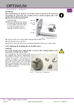
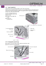
3.16
Fixing the lathe saddle
ATTENTION!
The cutting force produced during
facing, recessing or slicing proc-
ess may displace the lathe saddle.
Secure the lathe saddle using the
tightening screw.
Img.3-22:
Lathe saddle TU2506
Img.3-23:
Lathe saddle TU2807
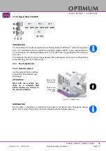
3.17
Turning tapers
3.17.1 Turning short tapers with the top slide
With the top slide short cone can be rotated. The scaling is performed up to 60° degree of
angle. It is also possible to adjust the top slide over the 60°- angular mark.
Loosen the two nuts at the left and right of the top slide.
Swivel the top slide.
Clamp the top slide again.
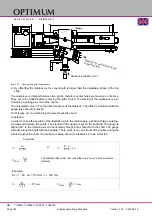
3.17.2 Turning tapers with the tailstock
The cross-adjustment of the tailstock is used for turning long, thin bodies.
Loosen the locking nut of the tailstock.
Unscrew the locking screw approximately half a turn.
By alternately loosening and tightening the two (front and rear) adjusting screws, the tailstock is
moved out of the central position. The desired cross-adjustment can be read off the scale.
First retighten the locking screw and then the two (front and rear) adjusting screws. Re-
tighten the adjusting screws of the tailstock.
Clamping screw
Clamping screw


