background image


50

Opticom Technologies Inc.  “L”  Series DVR 


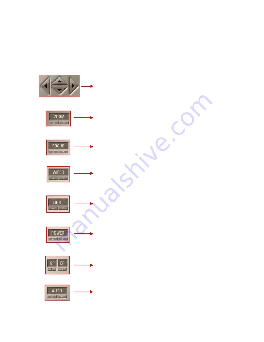
15.1 PTZ Button Description


Pan / Tilt control button : 
 A button to control the direction of the camera ( Up, Down, Left 
and Right) 


Image Zooming in/out control button: 
Used to zoom in and out of selected image 


Focus Control button: 
Used to control the focus of the selected camera. 


Wiper On/Off switch: 
Used to run/stop the operation of the wiper for cameras which are 
installed outside the location. 
 
 
Outside Light Switch button: 
Used to turn On/Off the housing light installed outside. 


Power switch button: 
Used to turn on/off power of peripherals like a fan. 


Set/release button at the starting/end point: 
Setting/releasing the starting and ending point of the automatic-
turning of the camera. 
 
 
Automatic-turning switch: 
Used to start/stop the auto-turning base 

Summary of Contents for Vista "L"ite Series DVR

Page 1: ...1 OPTICOM TECHNOLOGIES INC Vista L ite Series DVR Users Guide June 2004...

Page 2: ...ant operating and maintenance servicing instructions in the literature accompanying the appliance The Lightning flash with arrowhead symbol within an equilateral triangle is intended to alert the user...

Page 3: ...5 Before You Start 15 4 System Environment Setting 16 4 1 Power On 16 5 Current Time Setting 17 6 Program Start 18 7 Storage Configuration 19 7 1 Allocate Hard Drive Space 20 7 2 Delete Allocated Spac...

Page 4: ...nfiguration 39 12 3 Recording Schedule 42 13 Network Configuration 45 13 1 Server Configuration 46 13 2 User Registration 48 13 3 Current Session 49 14 ID Setup 50 15 PTZ Setup 51 15 1 Button descript...

Page 5: ...he she will be able to set the system according to the end user s request This User s Manual does not include explanations of peripheral equipment such as cameras pan tilt equipment monitors computer...

Page 6: ...ables random access with instant visual checking and the panoramic temporal search shows snap shots for specific camera to analyze every scene 2 times and 4 times fast video replay are also available...

Page 7: ...can be stored as a backup in well known formats on various media such as Neo Drive CD RW Removable Hard Disk DVD RW DAT and analog video Real time remote monitoring and control through the Internet N...

Page 8: ...pe Model VSL430 VSL1630 VSL16120 VSL16240 VSL16480 VSL16480B VSL16480C Intel i845PE OK OK OK OK OK OK OK Intel i865PE OK OK OK OK OK OK OK Intel i875P OK OK OK OK OK OK OK VIA P4X400 OK OK N A N A N A...

Page 9: ...9 Opticom Technologies Inc L Series DVR 3 2 Unpacking System Type Keyboard Power Cable Manual Mouse Computer Case Keys DVR Main System Handles Application CD...

Page 10: ...Power LED Indicates if the power is ON OFF 2 Run LED Displays the status of the system 3 HDD Hard Disk Drive LED A lamp indicating the operation of the HDD 4 Power Switch Turns the DVR system on or of...

Page 11: ...proof Therefore it is not to be used in the presence of flammable material 2 2 Proper use of this device depends on careful reading of all instructions and labels 3 3 Keyboard and mouse connectors to...

Page 12: ...ideo monitor 6 Coaxial video cable to the main system Connect the coaxial video cable to the main system by inserting one end of the BNC connecting cable into the back of the main system 7 Coaxial vid...

Page 13: ...rms a self test and displays a message if any errors are found Call the OPTICOM TECHNOLOGIES Technical Support if error messages are displayed E mail techsupport opticomtech com Phone 1 888 367 2288 W...

Page 14: ...dows system time the time already set at the factory needs to be set again with the appropriate time according to the user s geographic location Step 1 Click Settings Button Step 4 System Time Setup C...

Page 15: ...15 Opticom Technologies Inc L Series DVR Step 3 Data Storage Setup Button Click...

Page 16: ...16 Opticom Technologies Inc L Series DVR 6 Program Start Step 1 In the Windows main screen click Start Programs Vista L Series DVR Click Step 2 Auto Update Step 3 Main Screen...

Page 17: ...figuration Add or delete allocation space of the hard drive for recorded video data Available Hard Total Hard Drive Space Used Hard Drive To overwrite hard disk drive check this box If this box is not...

Page 18: ...18 Opticom Technologies Inc L Series DVR 7 1 Select Hard Drive Space for Recording...

Page 19: ...19 Opticom Technologies Inc L Series DVR Step 1 Click Setting Button...

Page 20: ...nc L Series DVR 8 Real Time Monitoring 8 1 Real Time Monitoring Screen 1 Video Input Status 5 Camera Display Status 2 Recording Status 6 Screen Split 3 Date Time Mode 7 Video Search 4 HDD Capacity Ind...

Page 21: ...detailed search Click to setup the Vista L Series DVR There are 6 types of system settings Click to move the camera up down left right to focus to enlarge to reduce Terminate the main program or the s...

Page 22: ...correctly for accurate video recording The playback of the video is performed according to this time and date In order to setup date and time use either the BIOS setup before system booting or the da...

Page 23: ...eries DVR 8 4 Split Screen Buttons Equally Split Screen Focused Split Screen Alternating Display and Full Screen Display The selected split screen icon is green According to the DVR model available sc...

Page 24: ...Search Mode select a camera for detailed search This camera indicates that the camera is activated In other wards the camera is currently displayed on the screen This icon indicates the camera is disp...

Page 25: ...ies DVR 8 6 Sensor Control Status Buttons Displays the sensor input status and control output The light is on when the sensor input is activated Active Sensor Input The light is on when the control is...

Page 26: ...26 Opticom Technologies Inc L Series DVR 9 Setting Password...

Page 27: ...27 Opticom Technologies Inc L Series DVR 10 Basic System Configuration...

Page 28: ...28 Opticom Technologies Inc L Series DVR 10 1 Video Source E mail Setup Sensor or Motion triggered channel pops up in a large screen Adjust for length of time in seconds...

Page 29: ...29 Opticom Technologies Inc L Series DVR Windows Sound and Audio Devices Properties open up Click OK to exit...

Page 30: ...l Select cameras to view through analog video out Default Select all cameras Reset Unselect all cameras 10 5 Sensor Link Alarm Setting VSL430 cs VSL1630 cs VSL16480 cs only support 4 alarms Connect up...

Page 31: ...ect up to 8 alarms Name individual alarms Select duration of the alarm 1 180 seconds Select wave file to be played for motion detection Select wav file to be played for sensor detection 4 wav files ar...

Page 32: ...ticom Technologies Inc L Series DVR 11 Video Channel Configuration Settings for Motion Detect Recording Quality Camera Display PTZ Alarm Sound and E mail Click ALL button to select or un select all ca...

Page 33: ...g Current view of selected camera Set motion detection sensitivity and region Motion detection region application size PEN size PEN1 PEN2 PEN3 Show Hide motion detection region on the view screen Remo...

Page 34: ...34 Opticom Technologies Inc L Series DVR 11 2 PTZ Configuration Select connected port Select PTZ address 11 3 Camera Configuration Setting...

Page 35: ...es Inc L Series DVR 11 4 Video Adjust 11 5 Video Quality 11 6 Alarm Sound E mail Link Setting Adjust video display recording properties Recording quality settings Enable Alarm Sound Enable Email notif...

Page 36: ...36 Opticom Technologies Inc L Series DVR 12 Recording Schedule Configuration Setup recording schedule recording frame rate pre alarm and post alarm Click ALL button to select or un select all cameras...

Page 37: ...as regardless of recording schedule 12 2 Recording Schedule Configuration If checked selected camera and timeframe will be recorded continuosly If checked and motion region is set selected camera and...

Page 38: ...f external light is attached to the camera the light will be powered on selected camera and timeframe Alarm Sound and Email notification will operate when motion or Sensor is detected Alarm Sound Emai...

Page 39: ...39 Opticom Technologies Inc L Series DVR...

Page 40: ...40 Opticom Technologies Inc L Series DVR 12 3 Recording Schedule example Continuous Recording 2 Motion Detection Recording Schedule...

Page 41: ...41 Opticom Technologies Inc L Series DVR 4 Motion Sensor Detection Recording Schedule...

Page 42: ...42 Opticom Technologies Inc L Series DVR 5 Continue Light ON Alarm ON Recording Schedule 6 Motion Sensor Detection Light ON Alarm ON Recording Schedule...

Page 43: ...43 Opticom Technologies Inc L Series DVR 13 Network Configuration Configure the network and clients...

Page 44: ...ame IP Address Client Video Transmission Quality configuration Enter DVR Server name Open Network Connections View page 46 for more info Current IP address Enable Web browse client TCP Service can be...

Page 45: ...ep 2 Select Internet Protocol TCP IP and click Properties Open Network Connections window to configure network Step 1 Right click on Local Area Connection Step 3 Fill in appropriate values in the And...

Page 46: ...ssword for Client to connect to Server Enter User Id Enter Username Enter Password Select User Level Live monitoring Live monitoring and playback Live monitoring playback and configuration Click ADD t...

Page 47: ...47 Opticom Technologies Inc L Series DVR 13 3 Current Session Shows current Client connection and Client s information disconnection of Client...

Page 48: ...48 Opticom Technologies Inc L Series DVR 14 ID Setup Change Password...

Page 49: ...49 Opticom Technologies Inc L Series DVR 15 PTZ Setup Operation of PTZ cameras...

Page 50: ...the selected camera Wiper On Off switch Used to run stop the operation of the wiper for cameras which are installed outside the location Outside Light Switch button Used to turn On Off the housing li...

Page 51: ...51 Opticom Technologies Inc L Series DVR 16 Recording Data Search Playback Search and Back up recorded data...

Page 52: ...ear and month of interest then the color coded dates are shown Play Play the selected video Fast Play Fast forward play the selected video Next Image Go to next image frame Pause Random Access Slider...

Page 53: ...channels and the row denotes the time One row represents a 30 minute time slot You can select time camera zones by using the keyboard or dragging the mouse When you use the keyboard the starting time...

Page 54: ...54 Opticom Technologies Inc L Series DVR 17 Detail Search Color Adjustment Play Restore Zoom Panning Thumbnail Button In Out Images...

Page 55: ...n Move Left Right Restore The image is restored to its original state All the zooming and moving actions are rolled back Zoom In Out With the zoom in out icon selected place the cursor on the image re...

Page 56: ...VR 17 3 Still Image Print Save 1x2 Layout 2x4 Layout 4x8 Layout Preview Selected Image Preview the selected image Here you can set up the print layout Selected Print Print the selected image You can p...

Page 57: ...57 Opticom Technologies Inc L Series DVR Save selected image Save the selected image onto a disk Show Hide Thumbnail Image Show or hide the thumbnail images on the screen...

Page 58: ...58 Opticom Technologies Inc L Series DVR 18 Panorama Data Search...

Page 59: ...59 Opticom Technologies Inc L Series DVR...

Page 60: ...elect the date of the video Select the channel of the video on on which a video clip is made which a video clip is made Make AVI File Quit Backup Backup Start Time Backup Stop Time Backup Location Ava...

Page 61: ...61 Opticom Technologies Inc L Series DVR 20 Client Program Installation...

Page 62: ...62 Opticom Technologies Inc L Series DVR 1 21 Remote Monitoring 2 21 1 Starting Client Program Step 1 My Computer double click C OpticomtechDVRs OpticomTechdvrs exe...

Page 63: ...63 Opticom Technologies Inc L Series DVR Step 4 Following window will open once password is entered...

Page 64: ...64 Opticom Technologies Inc L Series DVR Step 5 Enter Server information to the screen below and click ADD Click on Exit Button at the bottom to exit Setup 6 Click Connect Button to connect...

Page 65: ...65 Opticom Technologies Inc L Series DVR Step 7 Enter User ID and Password and click CONNECT to start Client program...

Page 66: ...66 Opticom Technologies Inc L Series DVR 21 2 Client Features 21 2 1 Main Client Screen Description...

Page 67: ...67 Opticom Technologies Inc L Series DVR 21 2 2 Recorded Data Search in Client Playback Screen Calendar Video Playback Control...

Page 68: ...68 Opticom Technologies Inc L Series DVR 21 2 3 Server Setting change in Client...

Page 69: ...69 Opticom Technologies Inc L Series DVR 21 2 4 PTZ control through Client Software...

Page 70: ...70 Opticom Technologies Inc L Series DVR 22 Web Client...

Page 71: ...in black and white Check video input type NTSC PAL Check if the connected camera is NTSC or PAL 3 DVR time does not match current time DVR time is set by Windows time Set time in BIOS or Windows to co...

Page 72: ...th motion detection Check for secure alarm connection at the alarm input Check power supply to Alarm Check if that particular alarm is enabled in the setting Check if motion detection region is set fo...

Page 73: ...ess etc Slide video property bar to set desired setting default setting is usually optimal 11 No e mail notification for motion detection Check if e mail address is correct Check if e mail server sett...

Page 74: ...when sensor is triggered during selected day and time 14 No recording in Continuous mode Check recording schedule for desired recording day and time 15 No recording in Motion Detection mode during mo...

Page 75: ...9 No display screen rotation even when the rotation time is set Check if rotation button is pressed in the main screen 20 No video in the external analog monitor Check for secure connection between th...

Page 76: ...or correct PTZ controller type and protocol Check for correct COM port selection for that particular PTZ controller contact camera supplier for further troubleshooting 23 Cannot view playback or chang...

Page 77: ...uld not be used until all repairs have been made and the unit is functioning properly and ready for use The owner of this product has sole responsibility for any malfunction resulting from improper us...

Page 78: ...tions must be observed during the operation of the system to avoid the possibility of injury This system is not explosion proof Therefore it is not to be used in the presence of flammable materials Th...

Page 79: ...ical support 5 A protective seal will be placed on the DVR for various reasons and shouldn t be tampered with It may void the warranty and a standard after service of the DVR will not be conducted if...

Page 80: ...other protective materials as is Shipping or carrying the DVR unit without its protective packaging materials may cause damage to the DVR HDD is weak in shock 3 When returning or shipping the DVR the...

Page 81: ...81 and or authorized agents with any questions...

Reviews: