


Installation – Virtual DDC
(Use this menu without DDC through CAT5e)
Important: Please use the installation procedure below. Improper or no
operation may result if the start-up sequence is not correctly followed.
Step 1
Check that the transmitter and receiver are turned off
. Set “DDC connection”
switch to “Virtual DDC” position on the front panel of the transmitter.
Step 2
For Self EDID programming;
a)
Plug the +24V power adapter to the power jack of the transmitter
,
and connect the adapter into AC outlet. Ensure “Power” and “EDID
PRGM” LEDs are turned ON.
b)
Push the “Self-EDID” button on the front side of Tx box.
The “EDID
PRGM” LED is turned ON after blinking twice
.
The “Status” LED is
turned ON.
Note: Please, DO NOT connect the Tx to the display without pushing the
“Self-EDID” button. The display may be damaged by unnecessary power
supply through pin16 of DVI connector.
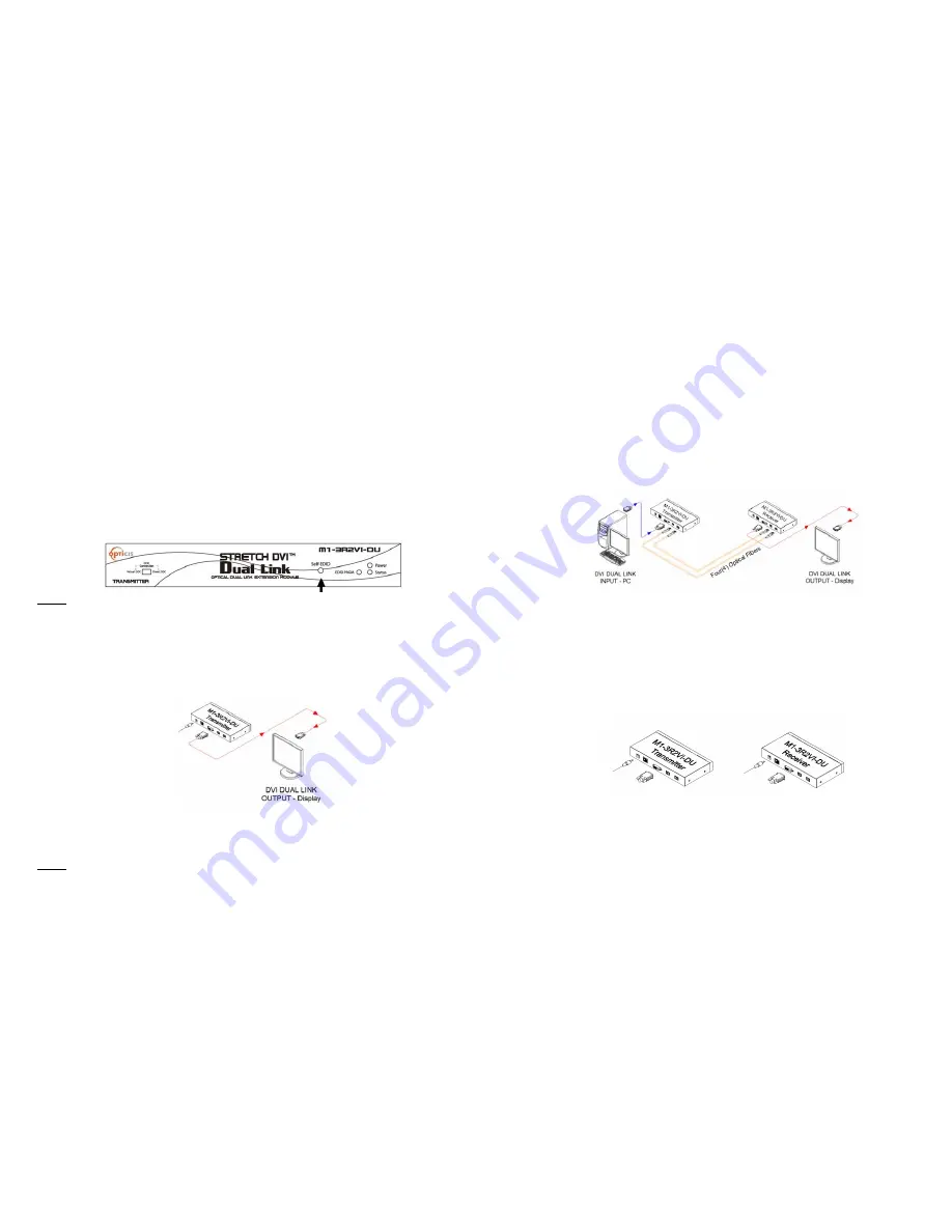
c)
Connect the powered transmitter to the powered display through
DVI dual link cable, not to the PC.
The LED blinking for 8~10 seconds
indicates reading the EDID data. “EDID PRGM” LED is turned OFF after
blinking and programming is done.
Figure 6 – Connection for Self-EDID programming
d) Disconnect the transmitter from the display and the power adapter.
Note:
If you want to change the display, please do again the step 2.
The EDID
factory default is programmed with the VESA standard of WQXGA
(2560x1600) 60Hz.
1-5 Installation (continued)
Step 3
Check that the transmitter and receiver are turned off and connect the
upstream Transmitter box to the DVI receptacle of PC by one dual link DVI
copper cable in the shipping group.
Step 4
In the same way as above, connect the Receiver box into the DVI receptacle
of the display by the other dual link DVI copper cable.
Step 5
Remove the module dust covers and connect each duplex LC fiber cable one
by one to each of 2 LC duplex receptacles of the Transmitter and Receiver
boxes, as shown in Fig. 7. Plug channel 1 to 1 and channel 2 to 2. Carefully
recheck polarities and ensure the duplex connectors are fully engaged.
Figure 7 – Connection of 4 LC fiber cables
Note : Connection for single link DVI
For single link DVI use, one duplex fiber or two simplex fibers is
required to be plugged to one port marked “Channel 1”. Note that self-
EDID programming is also applicable in connection for single link DVI.
Step 6
Connect two AC/DC power adapters to each of the DC input terminals of the
Transmitter and Receiver boxes.
Figure 8 – Connection of AC/DC power adaptor
Step 7
Plug the AC/DC power adapter into AC outlet. Turn ON the PC.
Tip 1:
After initial installation as guided in the above, we recommend you to
turn On and Off PC while all connections are set and the Tx/Rx boxes are
powered in.
1-6 Installation (continued)


