


4
Installation – Direct DDC
(Use this menu when DDC through CAT5e)
Important: Please use the installation procedure below. Improper, or no
operation may result if the start-up sequence is not correctly followed.
Step 1
Check that the transmitter and receiver are turned off. Set “DDC connection”
switch to “Direct DDC” position on the front panel of the transmitter.
Step 2
Connect the upstream Transmitter box to the DVI receptacle of PC through
one dual link DVI copper cable (included).
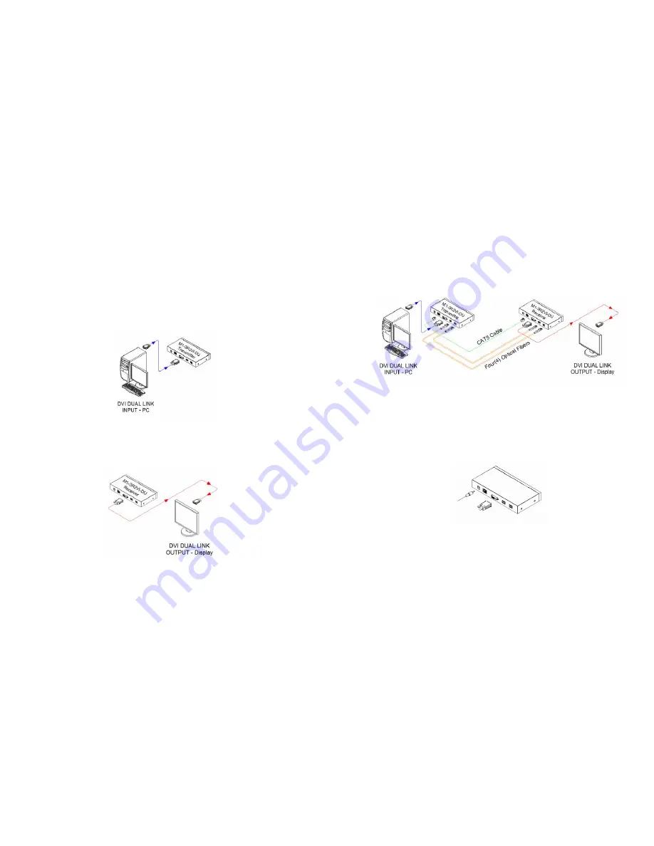
Figure 2 – Connection of DVI cable between Transmitter box and PC
Step 3
In the same way as above, connect the Receiver box into the DVI receptacle of
the display through the other dual link DVI copper cable.
Figure 3 – Connection of DVI cable between Receiver box and the display
Warning:
Please DO NOT look directly into the LC receptacles of the
Transmitter box, while it is turned on, although this product is strictly regulated
enough to operate under the Laser Class I, classified by CDRH/FDA for eye
safety.
1-3 Installation
Step 4
Remove the module dust covers and connect each duplex LC fiber cable one by
one to each of 4 LC receptacles of the Transmitter and Receiver boxes, as shown
in Fig. 4. Plug channel 1 to 1 and channel 2 to 2. Carefully recheck polarities and
ensure the duplex connectors are fully engaged.
Step 5
Connect each RJ-45C of the CAT5e cable to each RJ-45C receptacle of the
Transmitter and Receiver boxes.
Figure 4 – Connection of 4 LC fiber cables and a DDC cable
Note : Connection for single link DVI
For single link DVI use, one duplex fiber or two simplex fibers are required
to be plugged to one port marked “Channel 1”.
Step 6
Connect an AC/DC power adapter to the DC input terminal either of Transmitter
and Receiver boxes as your availability of AC outlets.
Figure 5 – Connection of AC/DC power adaptor
Step 7
Plug the AC/DC power adapter into AC outlet. Turn ON the PC.
Tip 1:
After initial installation as guided in the above, we recommend you to power
On and Off while all connections are set and the Tx/Rx boxes are powered in.
1-4 Installation (continued)


