background image

Pyrocam III

HR

 User Guide 

Document No. 50361-001 

Rev E 

7/18/2017 

Page 33 

STEP 3.


Disengage  the  two  screws  securing  the  bezel  to  the  motor  plate  as  shown  in 
Figure B.3. 

Caution: Use great care to ensure that the bezel does not slip or detach 
prematurely. If it contacts the detector, damage is very likely to occur.


STEP 4.


Carefully

 lift off the window bezel assembly. Be extremely careful not to cause 

damage or allow contaminates into the detector package. 


Figure B.3 Remove Bezel Assembly 

 
Reverse the above procedure to install a new window assembly. 


Summary of Contents for Pyrocam IIIHR

Page 1: ...Page 1 Pyrocam IIIHR User Guide For Sales Service or Technical Support Phone 435 753 3729 Fax 435 753 5231 Service Email service us ophiropt com Sales Email sales us ophiropt com Ophir Spiricon LLC 3...

Page 2: ...cel Visual Studio and XPS are registered trademarks of Microsoft Corporation LabVIEW and NI IMAQdx are registered trademarks of National Instruments Corporation 2015 2017 Ophir Spiricon LLC All Rights...

Page 3: ...System Installation 8 2 1 1 BeamGage Setup 8 2 1 2 Connections 8 2 1 3 Driver Installation 9 CHAPTER 3 SETUP AND OPERATION 10 3 1 Introduction 10 3 2 Overview of Pyrocam Controls 10 3 3 Pulsed Operati...

Page 4: ...ocam IIIHR Specifications 27 Pyrocam Dimensions 29 APPENDIX B PROTECTIVE BEZEL REMOVAL AND WINDOW INSTALLATION 31 APPENDIX C BAD PIXEL CORRECTION 34 Bad Pixel Correction Overview 34 Bad Pixel Correcti...

Page 5: ...is also compatible with National Instruments Vision Image Acquisition Software and any GenICam standard client CHAPTER 4 1 2 Models Spiricon offers the Pyrocam IIIHR in the following models all of whi...

Page 6: ...the optional bad pixel correction procedure Appendix D explains the optional gain correction procedure Appendix E contains a complete list of all Pyrocam models and accessories and Appendix F contain...

Page 7: ...r source that applies less than 240 Volts AC 50 60Hz between the supply terminals The supply output is a regulated 12Vdc that presents no electrical shock hazard The power supply has no user serviceab...

Page 8: ...with an electronic User Guide in multiple languages BeamGage also has a What s This help feature that can be used to quickly discover what the various controls do and how to manage the display featur...

Page 9: ...nnect the trigger source to this SMA connector An SMA to BNC adapter cable is supplied A TTL trigger pulse can trigger the Pyrocam The trigger is rising edge sensitive 2 1 3 Driver Installation The eB...

Page 10: ...only be used in combination with higher gain and frame averaging to extract the very weakest of images When operating in pulsed mode the Pyrocam must be externally triggered The Delay setting should...

Page 11: ...programmed for pulsed and chopped operation Two BP maps are created at the factory and are flashed into the Pyrocam s EEPROM memory The factory BP maps are also supplied as two files that can be reloa...

Page 12: ...icate the pixel coordinate of the currently selected pixel location The Manual mode is used to select dark dim or bright pixels one at a time The Peak mode is used to find pixels that indicate too bri...

Page 13: ...state whenever a GC table is loaded into the Pyrocam If this control is deactivated it indicates that the Pyrocam does not have a gain correction table programmed in its EEPROM The procedure for crea...

Page 14: ...pplies to both manually entered and automatically calculated factors Since bad pixels cannot normally be corrected within this range it is necessary to map the bad pixels before attempting to run the...

Page 15: ...he laser fires at a stable periodic rate of 3Hz to 125Hz Mode 2 can also be used to split out a single pulse from a periodic burst of laser pulses When the trigger frequency exceeds 125Hz the Pyrocam...

Page 16: ...riptions 3 3 2 1 Trigger Rate Stability Trigger rate stability is required for pulsed modes 2 and 3 For best results the trigger pulse repetition rate should be stable to within 200 s The Pyrocam will...

Page 17: ...If the trigger source is unstable or turns on and off some loss of uniformity shot to shot will likely result For best operation calibrate the Pyrocam at the trigger rate being used and recalibrate i...

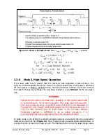
Page 18: ...so be patient Figure 3 2 Mode 2 Periodic 8 705 1 20 for 100 1 15 for 100 3 3 5 Mode 2 Periodic Burst Operation The Delay timer can be used to capture split out a single laser pulse from a burst of pu...

Page 19: ...WARNING Special care should be exercised when operating at high speed pulsed rates to avoid damage to the Pyrocam s detector High pulse rates with large ON time duty cycles can cause a significant amo...

Page 20: ...e rate output from the Pyrocam is limited by equipment bandwidths that are not accurately predictable Figure 3 4 Mode 3 High Speed 8 705 1 Use Mode 2 Periodic timing Example Laser pulse rate is 350Hz...

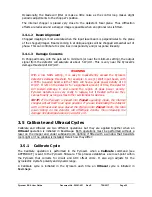
Page 21: ...of the camera s movement This deflection can bring the rotating blade into contact with the position encoder and or the imager s protective bezel risking costly damage to the chopper and the imager s...

Page 22: ...f time the detector will sustain damage in and around the region of peak power density Pyrocam detectors are very costly to replace but if treated with care they can last nearly as long as most other...

Page 23: ...o wait approximately 30 minutes after powering up the Pyrocam so that it reaches thermal equilibrium If a warm up period is not possible the Ultracal cycle should be rerun every 5 minutes or so during...

Page 24: ...id calibration cycle has been performed and is in effect the status indicator will appear GREEN As long as you do not disturb the Pyrocam set up or trigger timing the indicator will remain GREEN A RED...

Page 25: ...cquisition Software National Instruments Vision Acquisition Software 778413 35 can be used alone or with LabVIEW to control and capture images from the Pyrocam Follow these steps to capture images and...

Page 26: ...vi Grab vi Sequence vi Snap vi Low Level Grab Async vi Low Level Grab Raw Data vi Low Level Grab vi Low Level SDequence vi Low Level Snap vi The following examples do not work as is with the Pyrocam...

Page 27: ...T Pyrocam w o power supply 0 85kg 1 88 lbs DIMENSIONS See page 30 GENERAL Wavelength range 157nm to 355nm 1 06 m to 1000 m Detector Array Details Elements 25 600 160 x 160 Active Area 12 8mm x 12 8mm...

Page 28: ...d averaging 25 frames to 1Hz Saturation Power 3 0 W cm2 25Hz 4 5 W cm2 50Hz Damage Threshold Power Over entire array 2 W Peak Power Density 8 W cm2 Chopped mode 4 W cm CW in Pulsed mode PULSED OPERATI...

Page 29: ...Pyrocam IIIHR User Guide Document No 50361 001 Rev E 7 18 2017 Page 29 Pyrocam Dimensions w o chopper or cables...

Page 30: ...Pyrocam IIIHR User Guide Document No 50361 001 Rev E 7 18 2017 Page 30 Figure A 1 Trigger Input Circuit...

Page 31: ...or particles getting inside the package or by ESD Installation of a window can cause its own problems if not properly done The clearance between the chopper blade and the window is very small If the r...

Page 32: ...t CAUTION Do not bend or twist the chopper blade A bent or twisted blade can cause significant damage to the window the array the blade itself and various other components Figure B 2 Remove Chopper Bl...

Page 33: ...Use great care to ensure that the bezel does not slip or detach prematurely If it contacts the detector damage is very likely to occur STEP 4 Carefully lift off the window bezel assembly Be extremely...

Page 34: ...pixels can occur singly or they can occur in groups often referred to as clusters Bad pixels are most successfully repaired when they have a number of good neighbors where a neighbor is any adjacent...

Page 35: ...l appear in the 2D BeamGage display window Note that a description of the Bad Pixel Correction tools is described in section 3 2 Step by Step STEP 1 Click Start in BeamGage to collect live frames of d...

Page 36: ...bad pixel map to the Pyrocam Flash memory click on the Write Pixel List button The mouse pointer will become an hourglass while the new map is programmed into the Pyrocam When it returns to an arrow...

Page 37: ...OTE The relationship between bad pixel correction and gain correction is important to understand Bad pixel correction is usually turned on Bad pixel correction has a lesser impact on overall camera th...

Page 38: ...e with the gain set to a low setting Don t forget to Calibrate Ultracal the Pyrocam Open Utilities With the Pyrocam operating as described above click on the Gain Correction expansion button to access...

Page 39: ...completed STEP 5 To save the new gain correction table to a file highly recommended enter a file name in the Save and Load section and click the Save button A standard file naming window will appear M...

Page 40: ...Y III HR W GE 3 5 5 Pyrocam IIIHR window assembly Ge A R coated for 3 to 5 5 m SP90369 PY III HR W GE 10 6 Pyrocam IIIHR window assembly Ge A R coated for 10 6 m SP90370 PY III HR W GE 8 12 Pyrocam II...

Page 41: ...ID RO Device identifier serial number string 16 DeviceScanType RO Scan type of the sensor enum Linescan DeviceReset WO Resets the device to its power up state command ImageFormatControl Width RO Width...

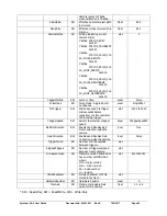
Page 42: ...PreTrigger RW Start array scan PreTrigger microseconds before negative or after positive the incoming trigger uint 3000 to 3000 ChopperSpeed RW Selects the internal chopper speed enum ChopperSpeed50 B...

Reviews: