background image

76

Zone 2 

With the Zone 2 function, you can enjoy one input 
source in the main room and a different source in another 
room.
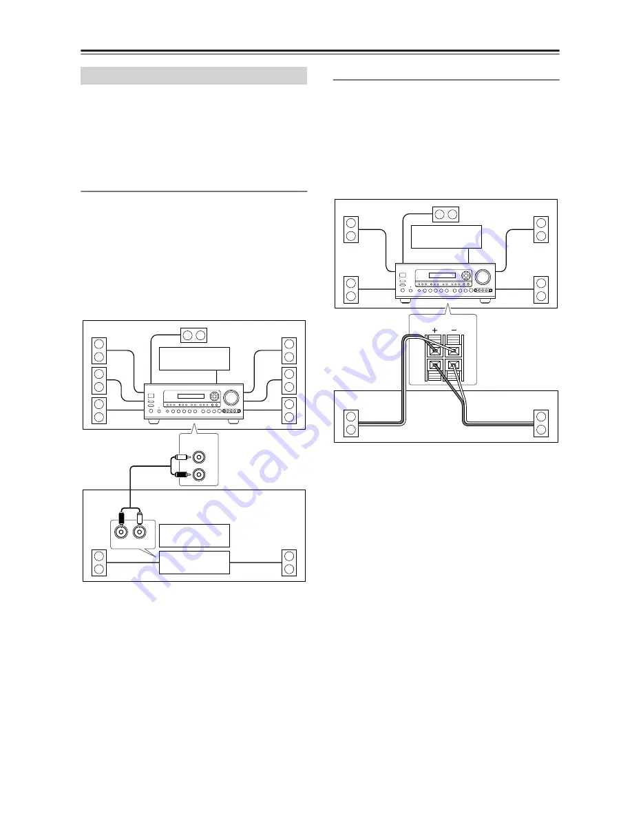
There are two connection methods: using a receiver/inte-
grated amp in Zone 2 or using only a pair of speakers in 
Zone 2.

Using a Receiver/Integrated Amp in Zone 2

With this connection method, you can use 7.1 surround 
sound in the main room and play a different AV source 
in Zone 2. The volume for Zone 2 is set on the receiver/
integrated amp.
• Use an RCA audio cable to connect the AV receiver’s 

ZONE 2 LINE OUT L/R jacks to an analog audio 
input on your receiver/integrated amp.

• Connect the Zone 2 speakers to the speaker terminals 

on the receiver/integrated amp.

Using Only Speakers in Zone 2

With this connection method, you can use 5.1 surround 
sound in the main room and play a different AV source 
in Zone 2. The volume for Zone 2 is set on the AV 
receiver.

• Set the Powered Zone 2 setting to Activated (see 

page 77).

• Connect your Zone 2 speakers to the AV receiver’s 

ZONE 2 SPEAKERS terminals.

Connecting Zone 2

R

L

IN

ZONE 2

LINEOUT

R

L

Main room

Zone 2

TV

TV

Receiver/

integrated amp

AV receiver

ZONE 2

SPEAKERS 

L

R

R

L

Main room

TV

Zone 2

AV receiver

Summary of Contents for TX-SR653E

Page 1: ...wing the instructions in this manual will enable you to obtain optimum performance and listening enjoyment from your new AV Receiver Please retain this manual for future reference Contents Introductio...

Page 2: ...aratus does not operate normally by following the operating instructions Adjust only those controls that are covered by the operating instructions as an improper adjustment of other controls may resul...

Page 3: ...cted Consult the dealer or an experienced radio TV technician for help For Canadian model NOTE THIS CLASS B DIGITAL APPARATUS COMPLIES WITH CANADIAN ICES 003 For models having a power cord with a pola...

Page 4: ...and is intended for home and other limited con sumer uses only unless otherwise authorized by Macrovision Reverse engineering or disassembly is prohibited Supplied Accessories Make sure you have the...

Page 5: ...o and S Video to compos ite video conversion 3 component video inputs 1 output 5 S Video inputs 3 outputs CinemaFILTER 3 Subwoofer pre out Tuner 40 AM FM DAB presets AM FM auto tuning RDS Radio Data S...

Page 6: ...Speaker Setup 38 About the Onscreen Setup Menus 41 Initial Setup 42 Digital Input 42 Component Video Setup 43 Minimum Speaker Impedance 43 TV Format Setup 44 Speaker Setup 45 Changing the Input Displa...

Page 7: ...telliVolume 73 Setting Preferences 73 Digital Input Signal Formats 74 Changing the Remote Controller s ID 75 Advanced Operations Using the Late Night Function Dolby Digital only 66 Using the CinemaFIL...

Page 8: ...ut source K DIGITAL INPUT button 42 74 This button is used to assign the digital inputs and to specify the format of digital input signals L RT PTY TP button 61 This button is for RDS Radio Data Syste...

Page 9: ...Pure Audio listen ing mode The indicator lights up when that mode is selected U TONE buttons 70 These buttons are used to adjust the bass and treble V Input selector buttons 52 These buttons are used...

Page 10: ...ts up when the AV receiver is tuned into a radio station AUTO This indicator lights up when the Auto Tun ing mode is selected and disappears when the Man ual Tuning mode is selected RDS This indicator...

Page 11: ...mponent video outputs such as DVD players F COMPONENT VIDEO OUT This component video output can be used to con nect a TV or projector with a component video input G AM ANTENNA 23 These push terminals...

Page 12: ...S Video composite video and analog audio Q VIDEO 2 IN OUT Here you can connect a VCR Input and output jacks include S Video composite video and analog audio R VIDEO 1 IN OUT Here you can connect a VCR...

Page 13: ...ype is used in the same room or the AV receiver is installed close to equipment that uses infrared rays the remote con troller may not work reliably Don t put anything such as a book on the remote con...

Page 14: ...receiver In SAT MD mode you can control an Onkyo MD recorder or a satellite TV receiver You must enter the appropriate remote control code first see page 80 Note Some of the remote controller operatio...

Page 15: ...ST TONE CH SEL LEVEL LEVEL buttons 49 These buttons are used to adjust the level of each speaker L MACRO buttons 84 These buttons are used with the Macro function M REMOTE MODE buttons 14 These button...

Page 16: ...func tions K AUDIO button This button selects foreign language soundtracks and audio formats e g Dolby Digital or DTS L OPEN CLOSE button This button is used to open and close the disc tray M CLEAR b...

Page 17: ...the elapsed time remaining time total time and so on G Playback buttons From left to right Previous Play Next Fast Reverse Pause Stop and Fast Forward H REC button This button is used to start record...

Page 18: ...ons select the previous or next playlist on the HDD compatible component J REPEAT button This button sets the Repeat function to One All or Off on the HDD compatible component K MENU button This butto...

Page 19: ...rs Subwoofer The subwoofer handles the bass sounds of the LFE Low Frequency Effects channel The volume and quality of the bass output from your subwoofer will depend on its posi tion the shape of your...

Page 20: ...osite video Left white Right red Yellow Right Wrong Video Cable Jack Description Component video cable Component video separates the luminance Y and color difference signals PR PB providing the best p...

Page 21: ...SUB WOOFER PRE OUT to an input on the amp Attaching the Speaker Labels The AV receiver s positive speaker terminals are color coded for ease of identification the negative speaker terminals are all bl...

Page 22: ...If you use 4 or 5 speakers connect each of the two surround speakers to the SURROUND SPEAKERS terminals Do not connect them to the SURROUND BACK SPEAKERS terminals Be careful not to short the positiv...

Page 23: ...careful that you don t injure yourself when using thumbtacks FRONT SPEAKERS CENTER SPEAKER SURROUND BACK SPEAKERS SURROUND SPEAKERS FRONT SURROUND CENTER CD VIDEO 3 VIDEO 3 VIDEO 2 VIDEO 2 VIDEO 1 VID...

Page 24: ...a must be grounded in accordance with local regulations to prevent electrical shock haz ards Using a TV FM Antenna Splitter It s best not to use the same antenna for both FM and TV reception as this c...

Page 25: ...ONITOR OUT jacks not the VIDEO 1 and VIDEO 2 OUT V and S jacks Note The TX SR653E can be set to upconvert com posite video and S Video input signals and output them from the COMPONENT VIDEO OUT see pa...

Page 26: ...DIGITAL IN jacks to an optical output on your TV as shown OR Use a coaxial digital audio cable to connect one of the AV receiver s COAXIAL DIGITAL IN jacks to a coaxial output on your TV as shown Usin...

Page 27: ...the DVD input source If you connect your DVD player to a different digital input you ll need to reassign the DVD input source see page 42 Using Analog Connections Even if your DVD player is connected...

Page 28: ...ER jacks to the 5 1 channel analog audio output on your DVD player as shown Alternatively use several analog audio cables ZONE 2 SPEAKERS AV RECEIVER MODEL NO TX SR653E L R FRONT SURROUND CENTER CD VI...

Page 29: ...ial output on your HDD DVD recorder as shown Connecting a VCR for Playback ZONE 2 SPEAKERS AV RECEIVER MODEL NO TX SR653E L R FRONT SURROUND CENTER CD VIDEO 3 VIDEO 3 VIDEO 2 VIDEO 2 VIDEO 1 VIDEO 1 I...

Page 30: ...n audio output on the recording VCR Notes The AV receiver must be turned on for recording Recording is not possible while it s in Standby mode If you want to record directly from your TV or play back...

Page 31: ...N 1 IN 2 IN 1 IN 2 IN 3 OUT COMPONENT VIDEO REMOTE CONTROL IN 2 IN 3 DIGITAL V S PB Y PR IR IN 12 V TRIGGER OUT ZONE 2 ANTENNA FM 75 AM ZONE 2 LINEOUT R L IN VIDEO 3 VIDEO OUT Satellite cable set top...

Page 32: ...CONTROL IN 2 IN 3 DIGITAL V S PB Y PR IR IN 12 V TRIGGER OUT ZONE 2 ANTENNA FM 75 AM ZONE 2 LINEOUT R L L R L R AUDIO OUTPUT IN VIDEO 3 Satellite cable set top box LD player etc STANDBY ON ZONE2 ZONE...

Page 33: ...DVD DVD IN IN IN IN OUT OUT IN IN R L IN 1 IN 1 IN 2 IN 1 IN 2 IN 3 OUT COMPONENT VIDEO REMOTE CONTROL IN 2 IN 3 DIGITAL V S PB Y PR IR IN 12 V TRIGGER OUT ZONE 2 ANTENNA FM 75 AM ZONE 2 LINEOUT R L D...

Page 34: ...URROUND CENTER CD VIDEO 3 VIDEO 3 VIDEO 2 VIDEO 2 VIDEO 1 VIDEO 1 IN OUT OUT IN IN OUT OUT TAPE SUB WOOFER MONITOR OUT COAXIAL OPTI CAL DVD DVD IN IN IN IN OUT OUT IN IN R L R L IN 1 IN 1 IN 2 IN 1 IN...

Page 35: ...T IN IN OUT OUT TAPE SUB WOOFER MONITOR OUT COAXIAL OPTI CAL DVD DVD IN IN IN IN OUT OUT IN IN R L IN 1 IN 1 IN 2 IN 1 IN 2 IN 3 OUT COMPONENT VIDEO REMOTE CONTROL IN 2 IN 3 DIGITAL V S PB Y PR IR IN...

Page 36: ...AV receiver The other jack is for connecting more compatible components Connect the AV receiver s jack to only OnkyoAV components Connecting to other manufacturer s AV components may cause them to mal...

Page 37: ...ctor but tons is pressed Before disconnecting the power cord from the wall outlet set the AV receiver to Standby Turning On the AV Receiver 1 Plug the power cord into an AC wall outlet The STANDBY ind...

Page 38: ...VD TUNER DISC ALBUM V4 TAPE RETURN 3 7 STANDBY ON ZONE2 ZONE 2 LEVEL PHONES PURE AUDIO MULTl CH TONE STEREO LISTENING MODE DISPLAY DIGITAL INPUT RT PTY TP MEMORY TUNING MODE RETURN TUNING PRESET ENTER...

Page 39: ...ant to select this option Continue with step 5 Check the Results Displays the measurement results for your reference Continue with How to Verify the Measurement Results described below Retry Retries m...

Page 40: ...nt results confirmation screen turn the volume up to an appropriate level and the frequency as high as it can go And then turn on the Direct switch if available For fur ther information see the manual...

Page 41: ...onnected to either of the MONITOR OUT jacks Because they appear on your TV they re large and clear making setup a breeze About the Onscreen Setup Menus Main menu Submenus p 45 p 43 p 48 p 49 p 58 p 72...

Page 42: ...input from the front panel terminals STANDBY ON ZONE2 ZONE 2 LEVEL PHONES PURE AUDIO MULTl CH TONE STEREO LISTENING MODE DISPLAY DIGITAL INPUT RT PTY TP MEMORY TUNING MODE RETURN TUNING PRESET ENTER...

Page 43: ...button The main menu appears onscreen 2 Use the Up and Down buttons to select 0 Initial Setup and then press ENTER The Initial Setup menu appears 3 Use the Up and Down buttons to select an input sele...

Page 44: ...pedance of any connected speaker is 4 ohms or more but less than 6 ohms 6 ohms Select if the impedances of all connected speakers are between 6 and 16 ohms 4 Press the SETUP button The setup menu clos...

Page 45: ...NTER SETUP TOP MENU MENU VOL CH DISPLAY PREV CH DIMMER SLEEP MUTING LISTENING MODE INPUT SELECTOR 3 2 MACRO 1 10 0 CLEAR 7 8 9 CD TUNER DISC ALBUM TAPE RETURN 1 11 2 10 2 1 RECEIVER 2 Use the Up and D...

Page 46: ...set to None this setting cannot be selected If the Surround setting in step 6 is set to Small this setting cannot be set to Large 8 Use the Up and Down buttons to select f SurrBack ch and then use th...

Page 47: ...o your speakers only if you have large front left and right speakers AND a sub woofer Note This procedure can also be performed on the AV receiver by using its SETUP button arrow buttons and ENTER but...

Page 48: ...2 Use the Up and Down buttons to select 2 Speaker Dis tance and then press ENTER The Speaker Distance menu appears Note Speakers that you set to No or None on the Speaker Configuration page page 45 c...

Page 49: ...c Speaker Setup function see page 38 10 11 12 REMOTE MODE HDD RECEIVER TAPE AMP DVD CD ZONE2 SAT TV VCR CABLE MD CDR RANDOM REC PLAYLIST TV VOL ENTER SETUP TOP MENU MENU VOL CH DISPLAY PREV CH DIMMER...

Page 50: ...D TUNER DISC ALBUM TAPE RETURN 1 7 2 6 2 1 RECEIVER ENTER ENTER 3 Use the Left and Right buttons to select Off Tone off response flat Auto The tone for each speaker is set automatically by the Automat...

Page 51: ...s the TAPE or VIDEO 3 input selector button so that TAPE or VIDEO 3 appears on the display 2 Press and hold down the TAPE or VIDEO 3 input selector but ton about 3 seconds to change the setting Repeat...

Page 52: ...e the AV receiver s input selector buttons to select the input source To select the input source with the remote controller press the RECEIVER button and then use the INPUT SELECTOR buttons On the rem...

Page 53: ...ess the CH SEL button on the remote controller and then press the LEVEL LEVEL buttons You can adjust the level between 12 dB and 12 dB Setting the Display Brightness Press the RECEIVER button and then...

Page 54: ...rpreting Surround Channel Values A The number of front channels 3 means front left front right and center B The number of surround channels 2 means surround left and surround right If there s surround...

Page 55: ...UTO indicator appears on the display 2 Press the TUNING Up or Down button Searching stops when a station is found TUNER Band Frequency STANDBY ON ZONE2 ZONE 2 LEVEL PHONES PURE AUDIO MULTl CH TONE STE...

Page 56: ...h the speakers Connecting the DAB Antenna 1 Screw the supplied DAB antenna onto the DAB connector Once theAV Receiver is ready for use you ll need to tune into a DAB station and adjust the position of...

Page 57: ...o tune appears on the display Returning to the previous station Pressing the JUMP button switches between current and previous stations Press the DISPLAY button repeatedly to cycle through the six dif...

Page 58: ...lified during play It is useful when you enjoy play with the volume set to the minimum at midnight or other occasions 1 Default Adjusts the dynamic range Adjustment with 1 is greater than with 1 2 1 2...

Page 59: ...lect a preset use the PRE SET buttons or the remote controller s CH but ton 1 Select the preset that you want to delete See the previous section 2 While holding down the MEM ORY button press the TUNIN...

Page 60: ...may be displayed intermittently or not at all Program Types Used in Europe PTY Using RDS Type Display Description None NONE No program type News reports NEWS Reports on current events and happenings C...

Page 61: ...TY TP MEMORY TUNING MODE RETURN TUNING PRESET ENTER SETUP DVD VIDEO 1 VIDEO 2 VCR 1 VCR 2 VIDEO 3 VIDEO 4 TAPE TUNER CD SETUP MIC S VIDEO VIDEO MASTER VOLUME VIDEO 4 INPUT L R AUDIO DIGITAL OFF STANDB...

Page 62: ...STEREO button This button selects the Stereo listening mode DIRECT button This button selects the Direct listening mode LISTENING MODE buttons Pressing these buttons repeatedly cycles through all of...

Page 63: ...VHS MD turntable radio cassette DTV etc DVD DTV etc DVD LD CD etc DVD Listening mode Pure Audio Direct Stereo Mono PLIIx Movie Music Game 3 3 If the SurrBack parameter is set to None or the Zone 2 spe...

Page 64: ...of sound The added drama and natural sound enhance the listening experi ence with CDs movies and games Dolby Pro Logic IIx has three modes of operation Movie mode for movies Music mode for listening...

Page 65: ...CDs Onkyo Original DSP Modes Orchestra Suitable for classical or operatic music The surround channels are emphasized in order to widen the stereo image In addition it simulates the natural reverberat...

Page 66: ...by Digital EX Dolby Pro Logic IIx Movie Dolby Pro Logic II Movie DTS DTS ES DTS Neo 6 Cinema DTS 96 24 DTS Neo 6 and DTS Dolby EX Using the Late Night Function Dolby Digital only 1 Press the RECEIVER...

Page 67: ...and use the LEVEL and LEVEL buttons to adjust the volume Speakers are selected in the following order Front Left Center Front Right Surr Right Surr Back Right Surr Back Left Surr Left Subwoofer You c...

Page 68: ...surround sound and DSP listening modes cannot be recorded Copy protected DVDs cannot be recorded You cannot record from the DVD analog multichannel input Various restrictions apply to digital recordin...

Page 69: ...input source dur ing recording that input source will be recorded STANDBY ON ZONE2 ZONE 2 LEVEL PHONES PURE AUDIO MULTl CH TONE STEREO LISTENING MODE DISPLAY DIGITAL INPUT RT PTY TP MEMORY TUNING MODE...

Page 70: ...ass or Treble 2 Use the TONE buttons to adjust STANDBY ON ZONE2 ZONE 2 LEVEL PHONES PURE AUDIO MULTl CH TONE STEREO LISTENING MODE DISPLAY DIGITAL INPUT RT PTY TP MEMORY TUNING MODE RETURN TUNING PRES...

Page 71: ...or there is not enough surround sound move it backward Center Width With this function you can adjust the width of the sound from the center speaker when using the Pro Logic II Music or Pro Logic IIx...

Page 72: ...to select a listening mode Only listening modes that can be used with each input signal format can be selected For Surround the listening mode specified on page 71 will be used The Last Valid option...

Page 73: ...Input Setup menu appears 3 Use the INPUT SELECTOR but tons on the remote controller to select the input source that you want to set 4 Use the Up and Down buttons to select a IntelliVolume If a compone...

Page 74: ...the AV receiver and remote controller see page 75 The default ID for both is 1 f IR IN Position When using a commercially available IR receiver use this setting to specify its location Main Select if...

Page 75: ...on both the remote controller and AV receiver see e Remote ID on page 74 The default ID for both is 1 Changing the Remote Controller s ID 1 Press and hold down the RECEIVER button and then press the T...

Page 76: ...to connect the AV receiver s ZONE 2 LINE OUT L R jacks to an analog audio input on your receiver integrated amp Connect the Zone 2 speakers to the speaker terminals on the receiver integrated amp Usi...

Page 77: ...DIO ALLST PLAYMODE VIDEO OFF REPEAT RANDOM REC PLAYLIST OPEN CLOSE CINEFLTR TV VOL ENTER SETUP TOP MENU MENU VOL CH DISPLAY PREV CH DIMMER SLEEP MUTING LISTENING MODE INPUT SELECTOR 3 2 MACRO 1 10 0 C...

Page 78: ...AM or FM you can use the remote controller s TUNER but ton to select the band To perform steps 1 and 2 on the AV receiver press the ZONE 2 button followed by an input selector button within eight sec...

Page 79: ...th Zone 2 In the following diagram an IR receiver picks up the infrared signals from the remote controller in Zone 2 and feeds them to the AV receiver in the main room via the connecting block On the...

Page 80: ...YMODE VIDEO OFF REPEAT RANDOM REC PLAYLIST OPEN CLOSE CINEFLTR TV CH TV VOL ENTER SETUP TOP MENU MENU VOL CH DISPLAY PREV CH DIMMER SLEEP MUTING LISTENING MODE INPUT SELECTOR 3 2 MACRO 1 10 0 CLEAR 1...

Page 81: ...d an analog audio cable RCA See page 36 for details 2 Enter the appropriate remote control code for the REMOTE MODE button DVD REMOTE MODE button 5002 Onkyo DVD player with CD REMOTE MODE button 6002...

Page 82: ...d H MENU ENTER RETURN Navigate menus on the satel lite cable receiver 10 11 12 REMOTE MODE HDD RECEIVER TAPE AMP DVD CD ZONE2 SAT TV VCR CABLE MD CDR STEREO SURR DIRECT SUBTITLE AUDIO ALLST PLAYMODE V...

Page 83: ...REMOTE MODE button for the mode in which you want to use the com mand press the ON button The Remote indicator lights up 2 On the AV receiver s remote con troller press the button you want to learn th...

Page 84: ...2 3 4 5 6 7 8 9 INPUT I ON STANDBY TV CD V1 V2 V3 MULTI CH DVD TUNER DISC ALBUM V4 TAPE RETURN 1 1 3 Remote indicator 1 While holding down the REMOTE MODE button for the mode you want to start with pr...

Page 85: ...ency Response 5 Hz 50 MHz Tuning Frequency Range 87 5 MHz 108 0 MHz Usable Sensitivity Stereo 22 2 dBf 75 IHF Mono 15 2 dBf 75 IHF S N Ratio Stereo 67 dB IHF A Mono 73 dB IHF A THD Stereo 0 5 1 kHz Mo...

Page 86: ...e a built in phono preamp you must connect one between it and the AV receiver If your turntable uses an MC cartridge you must connect an MC head amp or an MC transformer and phono equalizer Make sure...

Page 87: ...page 28 To select the DVD analog multichannel input press the MULTI CH input selector button Check the audio output settings on your DVD player About DTS signals When DTS program material ends and the...

Page 88: ...ol code Make sure to set the same ID on both the AV receiver and remote controller pages 74 and 75 Can t control other components If it s an Onkyo component make sure that the cable and analog audio c...

Page 89: ...functions don t work when Zone 2 is turned on Others The AV receiver contains a microcomputer for signal pro cessing and control functions In very rare situations severe interference noise from an ex...

Page 90: ...90...

Page 91: ...91...

Page 92: ...Groebenzell GERMANY Tel 49 8142 4401 0 Fax 49 8142 4401 555 http www eu onkyo com ONKYO EUROPE UK Office Suite 1 Gregories Court Gregories Road Beaconsfield Buckinghamshire HP9 1HQ UNITED KINGDOM Tel...

Reviews: