background image

5

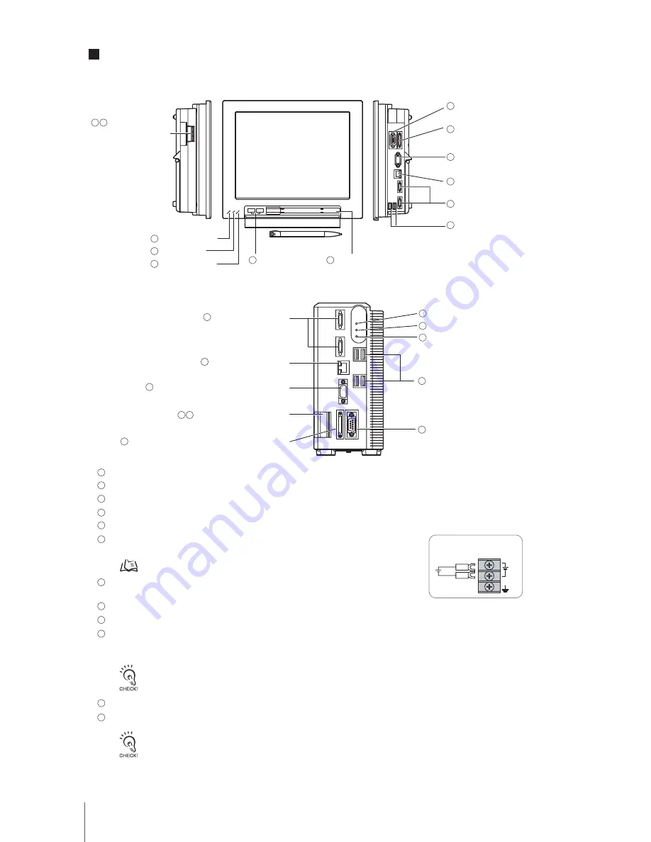
Lit while power is ON.

Lit while the controller is in Run Mode.

Lit when an error has occurred.

Connect the controller to external devices such as a sync sensor and PLC.

Connect cameras.

Connect a DC power supply. Wire the power supply unit independently  
of other devices. After wiring, replace the terminal cover.

Connect the ground wire. Make sure that the controller is grounded with a  
separate ground wire.

Connect a monitor.

Connect an external device such as a personal computer or PLC. 

Connect a track ball, mouse and USB memory. A total of four USB ports are provided and any of them can be 
used. However, when connecting two or more USB memories, do not connect them to adjacent ports. Doing so 
may cause the USB memories to come into contact, resulting in malfunction or damage.

Connect the controller to a personal computer.

A touch pen is stored. (Provided with the LCD integrated type only)

Camera connector

Camera connector

Ethernet connector

Ethernet connector

Monitor connector (analog RGB)

Monitor connector  
(analog RGB)

Power/ground terminal

POWER LED

USB connector

USB connector

RS-232C/RS-422 connector

RS-232C/RS-422 
connector

I/O connector (control lines, data lines)

I/O connector  
(control lines, data lines)

• The following items can be connected to USB ports.       • Commercially available track ball and mouse       • USB memory

• Never insert/remove USB devices during measurement. Doing so may affect measurement time.

Power Supply and Wiring p.3

Front view

Left-side view

Right-side view

Power/ 
ground terminal

RUN LED
ERROR LED

POWER LED
RUN LED

ERROR LED

USB connector

Box type  FZ2-350/FZ2-355/FZ2-550/FZ2-555

LCD integrated type FZ2-300/FZ2-305/FZ2-500/FZ2-505

Power Supply Wiring

Touch pen (holder)

24VDC

+

Component Names and Functions

6 7

1

2

3

1

2

3

10

4

4

5

5

6 7

8

8

9

9

10

10

11

11

1

2

3

4

5

6

7

8

9

10

11

12

12

• The touch pen must be stored so that the pen tip faces to the right when viewed toward the controller. 

• To remove the touch pen, push the left side (handle) of the pen to the rear. The pen

s right side (pen tip) will pop out, so 

hold and remove the pen.

Summary of Contents for Xpectia FZ2-30

Page 1: ...Vision Sensor Cat No 1842097 4A Xpectia FZ2 30_ FZ2 35_ FZ2 50_ FZ2 55_ INSTRUCTION MANUAL ...

Page 2: ... the following The FZ Series Vision Sensor must be operated by personnel knowledgeable in electrical engineering To ensure correct use please read this manual thoroughly to deepen your understanding of the product Please keep this manual in a safe place so that it can be referred to whenever necessary 㧖 The meaning of _ in model is described below 0 NPN I O type 5 PNP I O type 1842097 4A OMRON Cor...

Page 3: ...S AND SHOULD NOT BE RELIED UPON AS A SAFETY COMPONENT OR PROTECTIVE DEVICE FOR SUCH PURPOSES Please refer to separate catalogs for OMRON s safety rated products OMRON shall not be responsible for conformity with any standards codes or regulations that apply to the combination of products in the customer s application or use of the product At the customer s request OMRON will provide applicable thi...

Page 4: ...immediately after the power is turned OFF Dispose of this product as industrial waste Regulations and Standards The Controller conforms to the following standards EC Directive 89 336 EEC EMC EN standard European Standard EN61326 UL Standard UL61010 1 The following alert symbols are used in this manual Meanings of Alert Symbols The following alert statements apply to the products in this manual Eac...

Page 5: ...t Connecting Disconnecting Camera and Cables Always turn OFF the Controller s power before connecting or disconnecting a camera or cable Touching Signal Lines To prevent damage from static electricity use a wrist strap or another device for preventing electrostatic discharges when touching terminals or signal lines in connectors Handling a USB Memory To remove a USB memory make sure that data is n...

Page 6: ...standard accessory Right side view Controller Controller Monitor cable Camera cable Elastic camera cable FZ VSB 2 m 5 m 10 m Right angle camera cable FZ VSL 2 m 5 m 10 m Recommended Model By OMRON Corporation S8VS 12024 Use the monitor to check images and display the condition setting menus The Controller performs the image processing specified by the user settings and outputs the measurement resu...

Page 7: ...thernet connector Ethernet connector Monitor connector analog RGB Monitor connector analog RGB Power ground terminal POWER LED USB connector USB connector RS 232C RS 422 connector RS 232C RS 422 connector I O connector control lines data lines I O connector control lines data lines The following items can be connected to USB ports Commercially available track ball and mouse USB memory Never insert...

Page 8: ...d Output terminal COM IN COM OUT Input voltage ON current 1 ON voltage 1 OFF current 2 OFF voltage 2 ON delay OFF delay Internal circuit 12 to 24 V DC 10 5 mA min 8 8 V min 0 5 mA max 1 1V max 5 ms max 0 7 ms max Input signals STEP 1 ON current ON voltage This refers to the current or voltage values needed to shift from the OFF ON state The ON voltage value is the potential difference between each...

Page 9: ...rence between each of the input terminals and COM IN Output signals Output voltage Load current ON residual voltage OFF leakage current Internal circuit 12 to 24 V DC 10 45 mA max 2 V max 0 2 mA max Input voltage ON current 1 ON voltage 1 OFF current 2 OFF voltage 2 ON delay OFF delay Internal circuit 12 to 24 V DC 10 5 mA min 8 8 V min 0 5 mA max 0 8 V max 0 1 ms max 0 1 ms max Output voltage Loa...

Page 10: ...Connection Method Wiring RS 232C RS 422 Controller Use a shielded cable The maximum cable length is 15 m Use a compatible connector Recommended items RS CS control cannot be used Align the connector with the socket and press it straight into place then fix it with the screws on both sides of the connector XM2A 0901 XM2S 0911 OMRON Corporation OMRON Corporation Signal name SD RD GND Pin No 2 3 9 Si...

Page 11: ... 25 39 4 M4 Depth 6 Top face Bottom face 1 0 Mounting 1 2 3 Mounting the controller to the optional desktop stand The controller can be placed on a desk by attaching the optional desktop stand FZ DS to the rear of the controller For details refer to the instruction manual of the desktop stand Mounting the controller to the optional VESA attachment unit VESA compatible mounting of the controller is...

Page 12: ...18 54 39 4 M4 Depth 6 4 M4 Depth 6 4 M4 Depth 6 83 308 260 246 296 130 110 7 6 68 33 163 5 28 4 12 8 10 20 120 120 4 M3 Depth 6 20 120 120 7 6 Unit mm Unit mm Controller External Dimensions LCD integrated type FZ2 300 FZ2 305 FZ2 500 FZ2 505 Box type FZ2 350 FZ2 355 FZ2 550 FZ2 555 4 ...

Page 13: ...eakage current Noise resistance Vibration resistance Shock resistance Ambient temperature range Ambient humidity range Ambient environment Ground Degree of protection Environmental conditions according to IEC61010 1 Case materials Weight Controller Specifications General specifications ...

Reviews: