background image

Chapter 1: Viper ePLC Robot Quick Setup

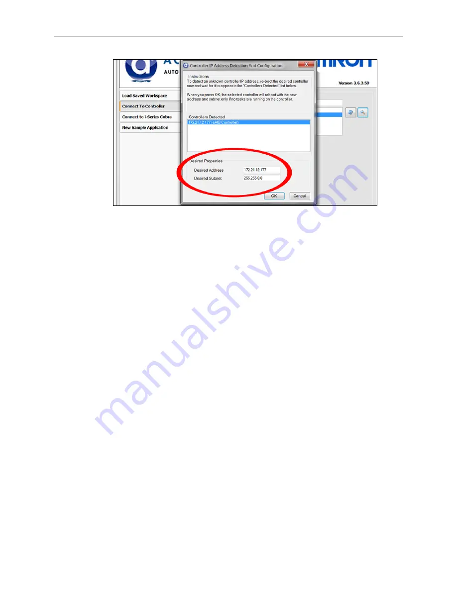
Figure 1-7. IP Addresses Detected

4. You can change the IP address and subnet mask in the Desired Address and Desired

Subnet fields, if needed.

5. Click OK. The ACE software will ask you to wait for the controller to reboot.

Configuring the Omron PLC

Refer to the EtherNet/IP Connection Guide (P649-E1-01) for configuring the Omron PLC to
work with Omron Adept robots. Refer to Resources on Omron Web Sites on page 3.

Using your PLC software, set the IP address for the PLC to connect to on the robot.

Enabling High Power

The details of enabling high power to the robot are covered in the EtherNet/IP Connection
Guide (P649-E1-01).

Once high power is enabled, the Robot Status Panel displays ON, and the amber Robot Status
LED is on.

1.7 Finding Additional Information

Installing Optional Equipment

For details on installing optional equipment, see the following topics in the Optional Equip-
ment Installation chapter of the Viper s650/s850 Robot User’s Guide:

l

Installing end-effectors

l

Connecting user air and electrical lines to user connection panel

l

Mounting external equipment on the robot

l

Mounting the robot solenoid option kit

Viper ePLC650/850 Quick Setup Guide, 13589-000 Rev D

Page 11 of 14

Summary of Contents for Viper 650 ePLC

Page 1: ...I600 E 01 Viper 650 850 ePLC Quick Setup Guide...

Page 2: ...viewed and revised Omron Adept Technologies Inc assumes no responsibility for any errors or omissions in this document Critical evaluation of this manual by the user is welcomed Your comments assist u...

Page 3: ...on Resources on the Support Disk l This guide along with three other ePLC robot quick setup guides l The Viper s650 s850 User s Guide Resources on Omron Web Sites On the Omron Industrial Automation we...

Page 4: ...ell Layout The following figure shows a simple workcell layout with a user supplied safety barrier and E Stops provided by the Front Panel and optional T20 pendant DC IN 24V GND AC 200 240V 1 XBELTIO...

Page 5: ...let This will prevent the robot from tipping over See the following figure Figure 1 2 Viper Robot Installation Mounting the Robot Mount the robot to a rigid surface that will prevent vibration and fl...

Page 6: ...60 R20 66 0 05 142 3 4X 12 THRU For M10 184 0 05 160 200 0 012 0 Diamond shaped pin Units are mm Figure 1 3 Mounting Hole Dimensions Figure 1 4 Viper ePLC Robot Movements Viper ePLC650 850 Quick Setup...

Page 7: ...g 04737 000 13323 000 standard eMB 60R H T20 Bypass Plug 10048 000 10055 000 standard T20 J T20 Adapter Cable 10051 003 10055 000 standard T20 K T20 Pendant option 10055 000 option L AC Power Cable op...

Page 8: ...de for location NOTE Ground conductor resistance must be 10 n a 5a Connect user supplied ground to SmartVision MX if used See SmartVision MX user s guide for location n a 6 Connect 200 240 VAC to AC i...

Page 9: ...Q P E K D N 3 85 264 VAC Universal Input Ethernet from PLC to eMB 60R FP Jumper Plug F Either Front Panel or FP plug must be used 3a 2a C Ethernet from eMB 60R to SmartVision MX R 9b 9a User supplied...

Page 10: ...the Viper ePLC robot using ACE software 1 Connect the PC and the robot either through a shared network or with an Ethernet cable between them 2 Start the ACE software 3 Click the Detect and Configure...

Page 11: ...to on the robot Enabling High Power The details of enabling high power to the robot are covered in the EtherNet IP Connection Guide P649 E1 01 Once high power is enabled the Robot Status Panel display...

Page 12: ...e System Operation chapter of the Viper s650 s850 Robot User s Guide l Robot Status LED Indicator l Status panel fault codes l Brake Release button located above or in diagnostic panel To move Joint 3...

Page 13: ......

Page 14: ...ADEPT TECHNOLOGIES INC 4550 Norris Canyon Road Suite 150 San Ramon CA 94583 U S A Tel 1 925 245 3400 Fax 1 925 960 0590 Regional Headquarters OMRON EUROPE B V Wegalaan 67 69 2132 JD Hoofddorp The Neth...

Reviews: