background image

Chapter 1: Viper ePLC Robot Quick Setup

DC

IN

24 V

GND

AC

200 -

240 V

Ø

1

XBEL

TIO

XIO

Servo

ENET

ENET

XSYSTEM

eMB-60R for

Viper ePLC

Robot

24 VDC, 6 A 

Power Supply

200-240 VAC 

10 A

single-phase 

AC Power 

Cable 

DC Power 

Cable 

Front Panel 
Cable

Front Panel

User-Supplied PC
running PLC
Programming Software

T20 Adapter 
Cable

XMCP Jumper Plug

XMCP

XFP

XUSR

XUSR Jumper Plug

eAIB
XSYSTEM 
Cable

Robot Interface 

Panel

XUSR for: 
- User E-Stop/Safety Gate
- Muted Safety Gate

The Jumper Plug is required if 
neither of these is used 

Ethernet from 

PC to PLC

T20 Bypass Plug

User-Supplied
Ground Wire

T20 Pendant (option)

Either T20 Pendant,T20 Bypass Plug, or 
XMCP Jumper Plug must be used

2

3

4a

A

B

G

H

J

4a

4

4

1

5

6

7

9

8

L

M

Q

P

E

K

D

N

3

85 - 264 VAC
Universal
Input

Ethernet from
PLC to eMB-60R

FP Jumper Plug

F

Either Front Panel or
FP plug must be used

3a

2a

C

Ethernet from eMB-60R
to SmartVision MX

R

9b

9a

User-supplied

Switch

SmartVision MX (option)

Camera

(option)

User-Supplied
Ground Wire

5a

7a

M

T

10

DC Power 
Cable 

S

PLC

DC

IN

24V

GND

AC

200 -
240V

Ø

1

XBEL

TIO

XIO

Servo

ENET

ENET

XSYSTEM

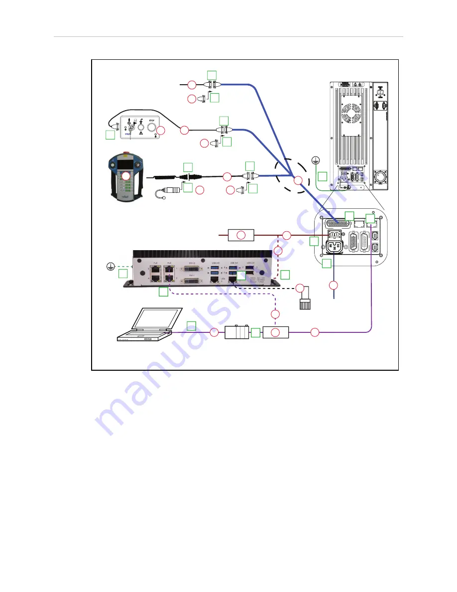
Figure 1-5. Configuration with Vision

1.6 Configuration

The user-supplied PLC and Viper robot are connected either through a shared network or via a
user-supplied Ethernet cable.

When the Viper ePLC robot is powered on and waiting for a PLC connection, the robot status
panel will display its IP address, two digits at a time.

The format will be:

IP xxx-xxx-xxx-xxx OK

NOTE

: If you can use the robot’s default IP address, then you can skip the ACE soft-

ware installation completely.

Viper ePLC650/850 Quick Setup Guide, 13589-000 Rev D

Page 9 of 14

Summary of Contents for Viper 650 ePLC

Page 1: ...I600 E 01 Viper 650 850 ePLC Quick Setup Guide...

Page 2: ...viewed and revised Omron Adept Technologies Inc assumes no responsibility for any errors or omissions in this document Critical evaluation of this manual by the user is welcomed Your comments assist u...

Page 3: ...on Resources on the Support Disk l This guide along with three other ePLC robot quick setup guides l The Viper s650 s850 User s Guide Resources on Omron Web Sites On the Omron Industrial Automation we...

Page 4: ...ell Layout The following figure shows a simple workcell layout with a user supplied safety barrier and E Stops provided by the Front Panel and optional T20 pendant DC IN 24V GND AC 200 240V 1 XBELTIO...

Page 5: ...let This will prevent the robot from tipping over See the following figure Figure 1 2 Viper Robot Installation Mounting the Robot Mount the robot to a rigid surface that will prevent vibration and fl...

Page 6: ...60 R20 66 0 05 142 3 4X 12 THRU For M10 184 0 05 160 200 0 012 0 Diamond shaped pin Units are mm Figure 1 3 Mounting Hole Dimensions Figure 1 4 Viper ePLC Robot Movements Viper ePLC650 850 Quick Setup...

Page 7: ...g 04737 000 13323 000 standard eMB 60R H T20 Bypass Plug 10048 000 10055 000 standard T20 J T20 Adapter Cable 10051 003 10055 000 standard T20 K T20 Pendant option 10055 000 option L AC Power Cable op...

Page 8: ...de for location NOTE Ground conductor resistance must be 10 n a 5a Connect user supplied ground to SmartVision MX if used See SmartVision MX user s guide for location n a 6 Connect 200 240 VAC to AC i...

Page 9: ...Q P E K D N 3 85 264 VAC Universal Input Ethernet from PLC to eMB 60R FP Jumper Plug F Either Front Panel or FP plug must be used 3a 2a C Ethernet from eMB 60R to SmartVision MX R 9b 9a User supplied...

Page 10: ...the Viper ePLC robot using ACE software 1 Connect the PC and the robot either through a shared network or with an Ethernet cable between them 2 Start the ACE software 3 Click the Detect and Configure...

Page 11: ...to on the robot Enabling High Power The details of enabling high power to the robot are covered in the EtherNet IP Connection Guide P649 E1 01 Once high power is enabled the Robot Status Panel display...

Page 12: ...e System Operation chapter of the Viper s650 s850 Robot User s Guide l Robot Status LED Indicator l Status panel fault codes l Brake Release button located above or in diagnostic panel To move Joint 3...

Page 13: ......

Page 14: ...ADEPT TECHNOLOGIES INC 4550 Norris Canyon Road Suite 150 San Ramon CA 94583 U S A Tel 1 925 245 3400 Fax 1 925 960 0590 Regional Headquarters OMRON EUROPE B V Wegalaan 67 69 2132 JD Hoofddorp The Neth...

Reviews: