


5
F3SJ-B-02TS
Quick Installation Manual
6. Mounting and Beam Alignment
For brackets other than top/bottom brackets (F39-LJB1) and intermediate brackets (F39-LJB2) as well as external dimensions
and mounting, refer to
F3SJ-B-02TS series user's manual
.
6-1. Mutual Interference Prevention
■
Series Connection
Up to three sets of F3SJ-B-02TSs can be series-connected. Series connection allows them to be used as a
safety light curtain, requiring only one set to be wired to a controller and preventing mutual interference.
If any one set of series-connected F3SJ-B-02TS is blocked, both of the safety outputs turn OFF. The indica-
tion LED for each F3SJ-B-02TS turns ON separately.
• Number of connections: Up to three sets
• Total number of beams: Up to 192 beams
• Connection cable length between two F3SJ-B-02TSs in series connection: 7 m max.
■
No Connection
Mutual interference is prevented in up to 3 sets, using interference light avoidance algorithm. If 4 or more
sets of F3SJ-B-02TS are installed and are not connected to each other, arrange them so that mutual interfer-
ence does not occur. If 2 sets are installed near each other, reflection from the surface of the F3SJ-B-02TS
may cause mutual interference. When mutual interference occurs, the safety outputs are turned OFF in a
moment or the F3SJ-B-02TS enters lockout. Combining countermeasures 1 to 4 shown below is effective.
1. Install a physical barrier between 2 sets
2. Alternate the direction of emission between 2 sets (alternation) If 2 sets are installed near each other,
reflection from the surfaces may cause mutual interference. For such a case, it can be improved by
reducing operating range through the setting tool (see Step 3).
3. Reducing operating range (setting change by the setting tool is required)
4. Keep sufficient distance between the F3SJ-B-02TSs so that mutual interference does not occur
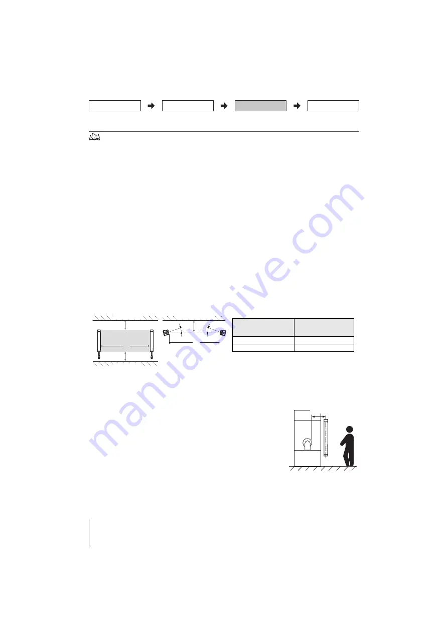
6-2. Distance from Reflective Surfaces
Install the sensor system at distance D or further from highly reflective surfaces such as metallic walls, floors,
ceilings, or workpieces, as shown below.
6-3. Safety Distance
How to calculate the safety distance specified by International Standard ISO 13855(European standard EN
ISO 13855)(Reference)
■
If a person approaches the detection zone of the F3SJ-B-02TS perpendicularly
S = K x T + C . . . Formula (1)
• S: Safety distance
• K: Approach speed to the detection zone
• T: Total response time of the machine and F3SJ-B-02TS
• C: Additional distance calculated by the detection capability of the F3SJ-B-02TS
<System that has detection capability of 30mm or less>
Use K = 2,000mm/s and C = 8 x (d - 14mm) in formula (1) for the calculation.
S = 2,000mm/s x (Tm + Ts) + 8 x (d - 14mm)
• S = Safety distance (mm)
• Tm = Machine's response time (s)
• Ts = Response time of the F3SJ-B-02TS from ON to OFF (s)
• d = Detection capability of the F3SJ-B-02TS (mm)
Please refer to the user's manual for calculation of following safety distance.
■
Possible circumventing by reaching over the detection zone
■
In case of horizontal approach of a human body to F3SJ-B-02TS's detection zone
■
How to calculate the safety distance specified by American standard ANSI B11.19(reference)
L
D
Detection zone
D
Emitter
Receiver
L
D
Emitter
Receiver
5°
5°
Reflective ceiling
Reflective floor
Reflective surface
Distance between an emitter
and a receiver
(operating range L)
Allowable installation
distance D
0.2 to 3 m
0.13 m
More than 3 m
L/2 x tan5 ° = L x 0.044 (m)
Hazard
Safety distance (S)
Mounting/Beam Alignment
Wiring
Function Selection
Pre-Operation Checklist /
Maintenance Checklists
Summary of Contents for Sti F3SJ-B P25-02TS Series
Page 15: ...F3SJ B P25 02TS OMRON Corporation 2017 2018 All Rights Reserved Original instructions...
Page 17: ...2 F3SJ B 02TS 2 3 3 4 5 10...
Page 18: ...3 F3SJ B 02TS 4 F3SJ B 02TS...
Page 22: ...7 F3SJ B 02TS 6 2 1 2 6 1...
Page 23: ...8 F3SJ B 02TS 3 4...
Page 24: ...9 F3SJ B 02TS 5 F39 LJB2 30 6 M3 8 M3 18 1 EMITTER RECEIVER...


