background image

NXR-ILM08C-EIT

3

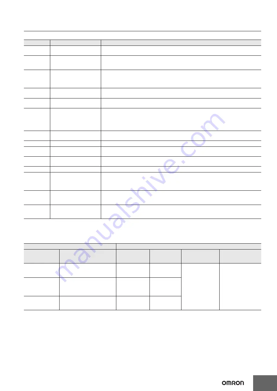
The components are described in the table below.

Applicable Support Software

The following table shows support software that can be used in the system configured with the NXR-series EtherNet/IP IO-Link Master Unit. For 
versions of support software, refer to Version Information on page 11.

Letter

Name

Function

(A)

Controller

This is an OMRON CPU Unit or a controller from another company, connected to the

IO-Link Master Unit through an EtherNet/IP adapter.

(B)

EtherNet/IP scanner

The EtherNet/IP scanner monitors the status of the connections with EtherNet/IP

adapters and exchanges I/O data with EtherNet/IP adapters through the EtherNet/IP

network. It refers to the 

originator

 when opening a connection.

(C)

EtherNet/IP adapter:

NXR-series 

IO-Link Master Unit

for EtherNet/IP

The NXR-series IO-Link Master Unit for EtherNet/IP is an EtherNet/IP adapter that provides IO-

Link master functions. You can connect IO-Link devices and non-IO-Link connected external 

devices to the NXR-series IO-Link Master Unit for EtherNet/IP. It exchanges data with IO-Link 

devices through IO-Link communications.

(D)

Unit/input power supply

The Unit/input power supply provides power to the IO-Link Master Unit for operation and interface 

with input devices. Connect an external power supply to the power supply connector (input).

(E)

Output power supply

The output power supply provides power for interface with output devices. Connect an external 

power supply to the power supply connector (input).

(F)

IO-Link device:

NXR-series 

IO-Link I/O Hub

The IO-Link device is a sensor, actuator, or other device that performs IO-Link communications 

with the IO-Link master.

It exchanges data with the NXR-series IO-Link Master Unit for EtherNet/IP in IO-Link 

communications. You can connect non-IO-Link connected external devices to the NXR-series IO-

Link I/O Hub.

(G)

Non-IO-Link connected 

External Device

The non-IO-Link connected external device is a sensor, actuator, or other device that handles 

ON/OFF signals that are not supported by IO-Link.

(H)

Ethernet switch

This is a relay device that connects multiple nodes.

(I)

Communications cable

EtherNet/IP cable

Use a double-shielded cable with aluminum tape and braiding of category 5 (100BASE-TX) or 

higher, and use straight wiring.

(J)

CX-ConfiguratorFDT

The CX-ConfiguratorFDT is the Support Software to configure and monitor IO-Link devices that 

are connected to the IO-Link Master Unit.

(K)

IODD files

These files contain IO-Link device definitions.

(L)

Network Configurator

The Network Configurator is the Support Software to configure an EtherNet/IP network. For the 

IO-Link Master Unit, it is used for the following purposes.

• Setting the device parameters of the IO-Link Master Unit

• Setting the connection between the EtherNet/IP scanner and the IO-Link Master Unit

(M)

EDS files

The EDS files contain information that is unique to the IO-Link Master Unit.

You can load EDS files into the Network Configurator or other Support Software for EtherNet/IP 

network setup to easily allocate data and view or change settings.

(N)

Support Software 

for the Controller

The Support Software is used to configure the Controller and EtherNet/IP scanner, create user 

programs, and perform monitoring, and troubleshooting. The Support Software depends on the 

Controller that you use.

IO-Link Master Unit connected to

Purposes and support software

Controller

EtherNet/IP Scanner

Creating user 

programs

Setting 

connections

Setting device 

parameters of 

IO-Link Master Unit

Setting and 

monitoring connected 

IO-Link devices

NJ/NX-series

CPU Unit

Built-in EtherNet/IP port on an 

NJ/NX-series CPU Unit or 

CJ1W-EIP21

Sysmac Studio

Sysmac Studio or 

Network 

Configurator

Network Configurator CX-ConfiguratorFDT

CJ/CP/CS-series

CPU Unit

• EtherNet/IP unit

CJ1W-EIP21 or CS1W-EIP21

• CJ-series CPU unit

Built-in EtherNet/IP port

CX-Programmer

Network 

Configurator

Controller from 

another 

manufacturer

EtherNet/IP Scanner

from another manufacturer

Software from 

another 

manufacturer

Software from 

another 

manufacturer

Summary of Contents for NXR-ILM08C-EIT

Page 1: ...rnet cables Communication quality of EtherNet IP Records the total number of received FCS errors which allows checking communication quality Communication quality of IO Link Records the total number o...

Page 2: ...port Software for the Controller L Network Configurator C EtherNet IP adapter NXR series EtherNet IP IO Link Master Unit F IO Link device NXR series IO Link I O Hub G Non IO Link connected External De...

Page 3: ...ted external device is a sensor actuator or other device that handles ON OFF signals that are not supported by IO Link H Ethernet switch This is a relay device that connects multiple nodes I Communica...

Page 4: ...chine Automation Controller System Controller CJ series NJ NX series Software FA Integrated Tool Package CX One Automation Software Sysmac Studio Product name Specifications Model Number of licenses M...

Page 5: ...HARTING K K M12 plug D coding male to M12 plug D coding male 4 Screw connector Straight straight 0 5 m 72MDm4MDm4005K 1 m 72MDm4MDm4010K 2 m 72MDm4MDm4020K 3 m 72MDm4MDm4030K 5 m 72MDm4MDm4050K 10 m...

Page 6: ...d appearance Manufacturer Specification No of cable conductors Connector Cable connection direction Cable length Model XS3W Socket and Plug on Cable Ends M8 Socket M12 Plug OMRON M8 socket A coding fe...

Page 7: ...85 with no condensation Altitude 2 000 m max Pollution degree 3 or less Conforms to IEC 61010 2 201 Noise immunity 2 kV on power supply line Conforms to IEC 61000 4 4 Overvoltage category Category II...

Page 8: ...distance 100 m or less Distance between nodes and between hub and node Topology Line Star Tree Ring Number of connected Units Line Star No restrictions Tree There is no restrictions in the number of...

Page 9: ...ations connectors and I O connectors M12 screw 0 5 to 0 6 N m Power supply connectors 7 8 inch screw 1 5 to 1 7 N m Unit mounting M5 screw 1 47 to 1 96 N m Rotary switch cover M3 screw 0 4 to 0 6 N m...

Page 10: ...mum load current 2 A pin Leakage current 0 1 mA max Residual voltage 1 5 V max ON OFF response time 1 0 ms max Short circuit protection Provided 3 Short circuit detection Provided 3 Current consumptio...

Page 11: ...twork Configurator CX ConfiguratorFDT NXR ILM08C EIT Ver 1 1 Ver 1 14 Ver 2 1 Ver 1 40 Ver 3 69 Ver 2 54 Ver 1 0 IO Link Master Unit Corresponding versions Model Unit version CPU unit version CS1W EIP...

Page 12: ...supply E Power supply connector output The connector for supplying Unit input power and output power from the local node to another node Use this connector when the power supply method is power supply...

Page 13: ...NXR ILM08C EIT 13 Dimensions Unit mm 16 5 6 5 5 5 Two M5 or 5 3 dia holes Mounting dimensions 14 2 24 2 37 26 8 19 2 38 47 5 14 5 17 45 62 26 7 97 7 122 7 147 7 172 7 208 7 240 19 2 32 8 45 5 227 0 2...

Page 14: ...mple for an IO Link device with digital outputs for pin 2 is shown below In this example the port is used in the following communications modes Pin 4 IO Link Mode pin 2 SIO DI Mode Power supply connec...

Page 15: ...and outputs for pin 2 is shown below In this example the port is used in the following communications modes Pin 4 IO Link Mode pin 2 Disabled 4 2 3 1 2 1 3 4 2 1 3 4 U IN P U IN P Power supply connect...

Page 16: ...Sensors In this example the port is used in the following communications modes Pin 4 SIO DI Mode pin 2 Disabled Three wire sensor PNP type 4 2 3 1 2 1 3 4 U IN P U IN P Power supply connector input I...

Page 17: ...k output device is shown below In this example the port is used in the following communications modes Pin 4 SIO DO Mode pin 2 Disabled 4 2 3 1 2 1 3 4 U IN P Non IO Link output device U IN P OUT P OUT...

Page 18: ...Master Unit The power supply connector output is not used This method does not cause voltage drop in through wiring cables or due to connection through IO Link Master Units Unit input power supply Ou...

Page 19: ...he power supply connector input of another IO Link Master Unit with a power supply cable In this way supply power with through wiring between the subsequent Units with power supply cables The power su...

Page 20: ...NS communications Sysmac Studio Version 1 Operation Manual W504 SYSMAC SE2 Learning about the operating procedures and functions of the Sysmac Studio Describes the operating procedures of the Sysmac S...

Page 21: ...her in no event shall liability of Omron Companies exceed the individual price of the Product on which liability is asserted Suitability of Use Omron Companies shall not be responsible for conformity...

Reviews: