4-7
4 Optics and Lighting
MicroHAWK F320-F / F330-F / F420-F / F430-F Smart Camera User Manual
4-4
MicroHA
W
K F
430-F
Externa
l Illum
ination
Con
trol an
d Wiring
4
4-
2-1 LED
Module
s
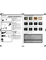
In Strobe mode, the external illuminator is strobed with the exposure of the camera to maximize light for
the short exposure times needed in dynamic applications.
ON/OFF allows the external illuminator to be enabled and disabled using the MicroHAWK F430-F’s I/O.
QX-1 Interface
Operation
Cable
1
Strobe
61-000218-01, Smart Series-to-QX-1, Strobe, NPN
2
ON/OFF
61-000207-01, Smart Series-to-QX-1, ON/OFF
3
Continuous ON
61-000204-01, Smart Series-to-QX-1, Continuous
Figure D
MAX Series Illuminator in a daisy
chain configuration. See figures
A, B, or C for the correct power
supply and signal connections for
your application.
1
4
4
4
3
Figure E
MAX Series Illuminators with QX-1 Interface Device.
Note: Figure E is not compatible with daisy chaining.
Powering more than one MAX via the QX-1 will exceed
the QX-1’s current capacity.
Summary of Contents for MicroHAWK F320-F
Page 1: ...Z433 E 02 84 9000402 02 User Manual MicroHAWK F320 F F330 F F420 F F430 F Smart Camera...
Page 35: ...1 Introduction 1 20 MicroHAWK F320 F F330 F F420 F F430 F Smart Camera User Manual...
Page 65: ...2 System Components 2 30 MicroHAWK F320 F F330 F F420 F F430 F Smart Camera User Manual PNP...
Page 71: ...2 System Components 2 36 MicroHAWK F320 F F330 F F420 F F430 F Smart Camera User Manual...
Page 91: ...4 Optics and Lighting 4 12 MicroHAWK F320 F F330 F F420 F F430 F Smart Camera User Manual...
Page 143: ...Appendices E 4 MicroHAWK F320 F F330 F F420 F F430 F Smart Camera User Manual...