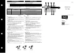
background image

K8AK-AW

5

Connections

Terminal Diagram

Note: 1.

Do not connect anything to terminals that are shaded in gray.

2.

There is no polarity for the DC power supply input.

3.

For the current input, you can input only from the C terminal and one other terminal.

4.

Refer to 

Setting Ranges and Wiring Connections

 on the I1, I2, and I3 current input terminals.

5.

Use the recommended ferrules if you use twisted wires.

6.

The K8AK-AW3 is designed to be used in combination with the OMRON K8AC-CT200L Current Transformer (CT).

Wiring Example

Directly Inputting a Current

Using a CT

• Always turn on the control power supply for the K8AK at least 2 seconds before turning on the power for the load.

K8AK-AW1 100-240VAC 

A B 

Control Output

Relay output

250 VAC, 5 A (resistive load)
30 VDC, 5 A (resistive load)

A

 Current Input

AW1

Relay Output

Common

B

 Power Supply Voltage

100 to 240 VAC

24 VAC/DC

(No polarity)

A1

A2

I1

11

12

14

Relay Output

Common

100 mA max.

500 mA max.

20m A max.

AW2

5 A max.

1 A max.

AW3

100 A max.

CT

CT

200 A max.

21

24

22

C

I2

I3

A1

A2

A1

A2

C

I2

I3

C

I2

I3

C

I2

I3

I1

I1

I1

21

24

22

11

12

14

C

I2

A1

A2

Load 

C

I2

A1

A2

Load 

Summary of Contents for K8AK-AS1 24VAC/DC

Page 1: ...ent Transformer CT Direct input is not possible Accessory Order Separately OMRON CT Commercially Available CTs If you use a commercially available CT do not exceed the overload capacity of the K8AK AW...

Page 2: ...mA AC DC 50 to 500 mA AC DC Approx 5 Direct input Continuous input at 120 of maximum input 1 s at 150 0 to 100 mA AC DC I2 COM Approx 1 Direct input 0 to 500 mA AC DC I3 COM Approx 0 2 Direct input K...

Page 3: ...puts ALM Red Input impedance Refer to Input Range on previous page Output relays Two SPDT relay outputs normally closed operation Output relay ratings Rated load Resistive load 5 A at 250 VAC 5 A at 3...

Page 4: ...minals Between input terminals and output terminals Dielectric strength 2 000 VAC for one minute Between external terminals and case Between power supply terminals and input terminals Between power su...

Page 5: ...h the OMRON K8AC CT200L Current Transformer CT Wiring Example Directly Inputting a Current Using a CT Always turn on the control power supply for the K8AK at least 2 seconds before turning on the powe...

Page 6: ...AL1 Contact b for the approx 1 second interval immediately after the K8AK control power supply is turned on After that a switch to contact a will be made as an overcurrent state is no longer present A...

Page 7: ...K8AK power supply voltage Power ON Undercurrent AL2 contacts 21 24 Undercurrent set value AL2 30 of AL1 current set value Overcurrent AL1 contacts 11 14 Lit AL2 alarm indicator AL1 alarm indicator Ove...

Page 8: ...ng time 0 1 to 30 s t Operating time 0 1 to 30 s t t Delay 250 ms reference value Delay 250 ms reference value Delay 250 ms reference value Delay 250 ms reference value Flashing Flashing Power ON lock...

Page 9: ...ched the same level Use this as a guide to set the current The maximum setting range will differ depending on the model and the input terminal Example K8AK AW3 Using Input Terminals I3 COM The maximum...

Page 10: ...de to set the startup lock time The startup lock time will start when the input current reaches 30 or more of the set value Use startup lock time to prevent unwanted operation e g as a result of inrus...

Page 11: ...figure for information on the motor startup current For a motor with a rating of 5 A the startup current will be approximately 30 A The startup current will exceed the overload capacity rating 150 for...

Page 12: ...cified torque of 0 49 to 0 59 N m Use of the product beyond its life may result in contact welding or burning Make sure to consider the actual operating conditions and use the product within its rated...

Page 13: ...ifficult to see 15 Do not use the product if it is accidentally dropped The internal components may be damaged 16 Be sure you understand the contents of this catalog and handle the product according t...

Page 14: ...MEMO 14...

Page 15: ...CONNECTED WITH THE PRODUCTS WHETHER SUCH CLAIM IS BASED IN CONTRACT WARRANTY NEGLIGENCE OR STRICT LIABILITY Further in no event shall liability of Omron Companies exceed the individual price of the Pr...

Page 16: ...0169 U S A Tel 1 847 843 7900 Fax 1 847 843 7787 Regional Headquarters OMRON EUROPE B V Wegalaan 67 69 2132 JD Hoofddorp The Netherlands Tel 31 2356 81 300 Fax 31 2356 81 388 Contact www ia omron com...

Reviews: