

Drive Goods
Relay Terminal Block with Brake Contact Output
Model Name
DG2BK1TB-
□
-
□
User’s Manual
Before Using the Product
Thank you for purchasing these Drive Goods product.
Before using the product, this document and our MEEFAN homepage obtain
the User
’s Manual of the publication, and please read the following items.
・
SAFETY PRECAUTIONS
・
FOR YOUR SAFETY
Please read the User
’s Manual of the homepage publishing, and use details
correctly after understanding the function and the performance of this product
enough.
MEEFAN homepage URL
http://www.mee.co.jp/sales/fa/meefan/
● SAFETY PRECAUTIONS ●
(Always read these precautions prior to use.)
Do not attempt to install, operate, maintain, or inspect this product until you have carefully read through
this instruction manual and relevant documents and can use the equipment correctly. Do not use this
product until you have a full knowledge of the equipment, safety information, and instructions. In this
manual, the safety instruction levels are clas
sified into "WARNING" and "CAUTION.”
WARNING
Indicates that incorrect handling may cause hazardous conditions,
resulting in death or severe injury.
CAUTION
Indicates that incorrect handling may cause hazardous conditions,
resulting in minor or moderate injury or property damage.
Under some circumstances, failure to observe the precautions given under "
CAUTION" may lead to
serious consequences. Observe the precautions of both levels because they are important for personal
and system safety.
After reading this manual, keep the manual in a safe place for future reference.
1. Electric Shock Prevention
WARNING
Make sure that all wiring work and inspections are performed by professional engineers.
Do not damage, apply unreasonable stress to, place heavy objects on, or pinch the cables. Doing so
results in the risk of electric shock.
To avoid electric shock, insulate the connection area of the power supply terminal.
Be sure to shut off all phases of the external power supply used by the system before performing work
such as installation and wiring. Failure to do so results in the risk of electric shock and product damage.
2. Fire Prevention
CAUTION
Be sure to install this product in a non-flammable object. Directly installing the product in a flammable
object or installing the product near a flammable object results in the risk of fire.
Do not allow any conductive foreign objects, such as a screw or metal fragments, or flammable foreign
objects, such as oil, to enter the product interior.
3. Injury Prevention
CAUTION
Be careful to connect terminals correctly. Failure to do so results in the risk of explosion, damage, and
the like.
Do not mistaken the polarity (positive and negative charges). Doing so results in the risk of explosion,
damage, and the like.
4. General Precautions
Also note the following precautions. Incorrect handling may cause failure, injury, electric shock, and the
like.
(1) Transport and Installation
CAUTION
This product is a precision instrument. During transport, avoid impacts larger than those specified in
general specifications. Failure to do so results in the risk of failure.
Do not stand or rest heavy objects on the product.
Do not install or operate units that are damaged or have missing parts.
This product is a precision instrument. Do not drop or apply strong impact to the product.
Use this product in an environment that reflects the general specifications set forth in the User’s Manual.
Usage in an environment outside of the scope of the general specifications results in the risk of electric
shock, fire, malfunction, product damage, and/or product deterioration.
When handling the product, be careful of sharp areas such as product corners.
Be sure to place this product inside a metal control panel.
Reliably secure the module using a DIN rail or screws. If the module is not properly mounted, risk of
malfunction, failure, and falling results. If using the product in an environment with high vibration, secure
the product with screws.
Tighten the screws within the specified torque range. Loose screws results in the risk of falling, a short
circuit, and malfunction. Excessively tightened screws may damage the screws and product, resulting in
the risk of falling, a short circuit, and malfunction.
Fumigants that contain halogen materials such as fluorine, chlorine, bromine, and iodine used for
disinfecting and protecting wooden packaging from insects will cause malfunction in Mitsubishi Electric
Engineering products. Please take necessary precautions to ensure that residual fumigants do not enter
the product, or treat packaging with methods other than fumigation (heat method, etc.). Additionally,
disinfect and protect wood from insects before packing.
(2) Wiring
CAUTION
This product is a Mitsubishi Electric general-purpose AC servo amplifier MR-J4-B and MR-J3-B series
dedicated product. Do not use the product with any servo amplifier or servo motor with an
electromagnetic break other than the MR-J4-B and MR-J3-B series.
Be sure to wire the product correctly. Failure to do so results in the risk of unexpected servo motor
operation.
The connection drawings in this manual are based on a sink interface, unless otherwise specified.
Be careful to properly set the orientation of the diodes for surge absorption, which are attached to the
DC relay for servo amplifier control signal output signals. Incorrect orientation results in the risk of the
servo amplifier failure, which can cause signal output failure and malfunction of protective circuits such
as emergency stop.
Always verify that the wiring is properly secured to the terminal block. Failure to adequately secure the
wiring results in the risk of poor contact, which can cause heat generation from the wiring and terminal
block.
Properly connect the wiring to the module after first verifying the module rated voltage and terminal
layout. Inputting or connecting the power supply to voltage that differs from the rated voltage and
miswiring result in the risk of fire and product failure.
Securely install the connector to the module. Failure to do so results in the risk of malfunction.
Be sure that foreign matter such as dust and wire shavings does not enter the module interior. Failure to
do so results in the risk of fire, failure, and malfunction.
CAUTION
Be sure to secure the power lines and cables connected to the module by placing them in a duct or
clamping them. If not, dangling cables may swing, move, or inadvertently be pulled, resulting in damage
to the module or cables, or malfunction due to poor cable connection.
When disconnecting the cable connected to the module, do not pull the cable by the cable part. For
cables with connectors, take hold of the connector connected to the module and then disconnect the
connector. For cables connected to the terminal block, unlock the terminal board spring lock and then
disconnect the connector. Pulling the connected cable may result in malfunction or damage to the
module or cable.
When connecting the servo amplifier, first verify that the product configuration is correct. Connecting the
servo amplifier with a wrong configuration results in the risk of failure and malfunction.
Securely mount the relay module to the module. Incorrect mounting results in the risk of damage, falling,
and malfunction due to poor contact. Additionally, be sure to attach and detach the relay module
following the correct procedure. Failure to do so results in the risk of damage, falling, and malfunction
due to poor contact.
(3) Usage
CAUTION
Do not disassemble, repair, or modify the product.
Never attempt to burn or disassemble the product. Doing so may cause generation of a poisonous gas.
Be careful when changing the output device assignments in servo amplifier parameters. Changing the
MBR (electromagnetic brake interlock) signal assignments, in particular, may cause unexpected
operation of the servo motor, damage, falling, and malfunction.
Make sure to set up external safety circuits outside the product to ensure safe system operation even
during external power supply problems or servo amplifier or product failure. Otherwise, erroneous output
or malfunction may cause serious accidents.
Relay or other similar failure may cause output to remain ON or OFF. Be sure to provide a circuit outside
the product that monitors output signals that may lead to serious accidents.
When a load current exceeding the current rating or an overcurrent caused by a load short-circuit flows
for a long time, it may cause smoke and fire. To prevent this, provide an external safety circuit.
(4) Emergency Handling
CAUTION
Connect the emergency stop switch to the EMG1 terminal and EMG2 terminal to ensure that the
electromagnetic brake activation output is linked to the external emergency stop switch.
(5) Maintenance and Inspection
CAUTION
Before removing or installing the module, cut off all phases of the power supply externally. Failure to do
so may cause module failure, malfunction, or damage.
Connection/disconnection of the module and cables after the first use of the product shall be limited to
50 times. (JIS B 3502 compliant)
Before handling the module, touch a grounded metal object to discharge the static electricity from your
body. Failure to release the static electricity may cause the module to fail or malfunction.
(6) Disposal
CAUTION
When disposing of this product, treat it as industrial waste.
1. Over view
This User’s Manual describes the specifications of the relay terminal block with brake contact
output that is used in combination with the Mitsubishi Electric general-purpose AC servo amplifier
MR-J4-B series and MR-J3-B series.
2. GENERAL SPECIFICATIONS
Item
Environment Conditions
Ambient
temperature
Operating
0°C to 55°C (non-condensing)
Storage
-20°C to 65°C (non-condensing)
Ambient
humidity
Operating
90% RH or less (non-condensing)
Storage
Environment
Indoors (not exposed to direct sunlight), free of corrosive gas, combustible
gas, oil mist, and dust
Elevation
Within 1000m above sea level
Vibration resistance
5.9m/s
2
, 10Hz to 55Hz (X, Y, and Z directions)
3. PERFORMANCE SPECIFICATIONS
Model name
DG2BK1TB DG2BK1TB-D KG2BK1TB-P01 DG2BK1TB-P01-D
Connected servo amplifier
MR-J4-B series, MR-J3-B series
Compatible servo motor capacity
0.05kW to 22kW
Servo amplifier interface connector
MDR20P connector
Control logic
Sink logic
Source logic
External
signal relay
terminal
block
Terminal area
Recommended tool: SZF0-0, 4x2, 5 (Phoenix Contact) or
equivalent product
No. of terminals: 11P, 3.5-mm pitch, No. of line insertions: 1 per
insertion port
Compatible wiring
Single wire, base wire: 0.2mm
2
to 1.5mm
2
, AWG24 to AWG16
Brake output
terminal
block
Terminal area
Recommended tool: SZF0-0, 4x2, 5 (Phoenix Contact) or
equivalent product
No. of terminals: 6P, 3.81-mm pitch, No. of line insertions:
1 per insertion port
Compatible wiring
Single wire, base wire: 0.2mm
2
to 1.5mm
2
, AWG24 to AWG16
External
power supply
For servo amplifier interface
Voltage: 24 VDC ± 10%, Current capacity: 0.3A (max)
For electromagnetic brake
Voltage 24 VDC 0/-10%, Current capacity 1.43A (max)
MBR signal
relay
Response
time
OFF
ON
10ms or less
ON
OFF
5ms or less
Mechanical service life
50 million times or more (switch frequency: 180 times/minute)
Electrical service life
100,000 times or more (resistance load)
Operation display
LED illumination display at relay coil ON
Socket
Yes (relay module replaceable)
Overseas
compliant
standards
UL standards
UL61800-5-1
Module installation
Screw/
DIN rail
DIN rail
Screw/
DIN rail
DIN rail
Installation
screws
Screw size
M4 x 0.7mm
x 10mm or
greater
-
M4 x 0.7mm x
10mm or
greater
-
Tightening torque
78 to
118N
cm
78 to 118N
cm
Compatible DIN rail
TH35-7.5Fe, TH35-7.5Al (JIS C2812 compliant)
Weight
Approx. 57g Approx. 56g
Approx. 57g
Approx. 56g
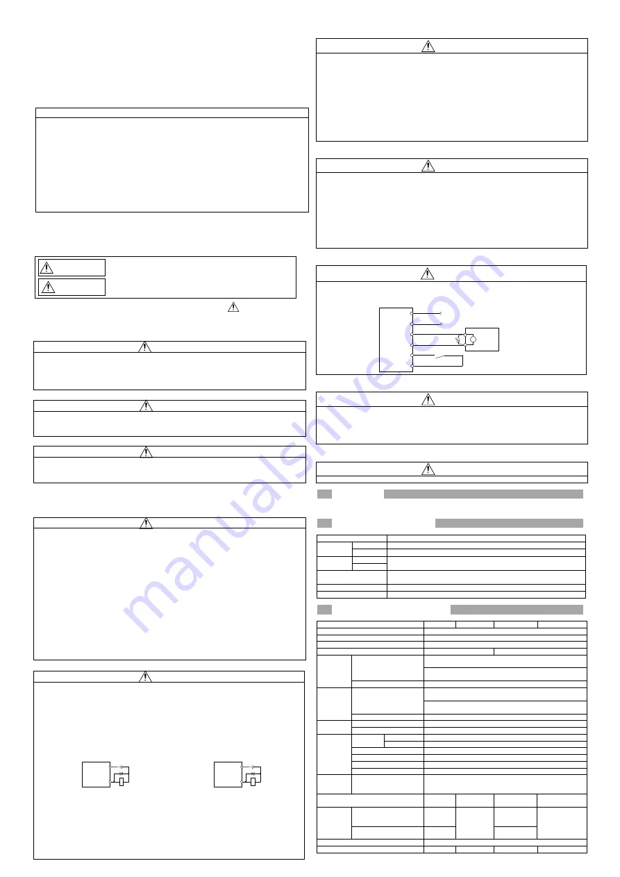
Relay terminal block with brake
contact output
DOCOM
Control output
signal
24 VDC
RA
With sink output interface
Connect the emergency stop switch
Relay terminal block with brake
contact output
24V
0V
B1
B2
EMG1
EMG2
TE2
U
B
24 VDC
Servo motor
Electromagnetic
brake
DOCOM
Control output
signal
24 VDC
Relay terminal block with brake
contact output
RA
With source output interface


