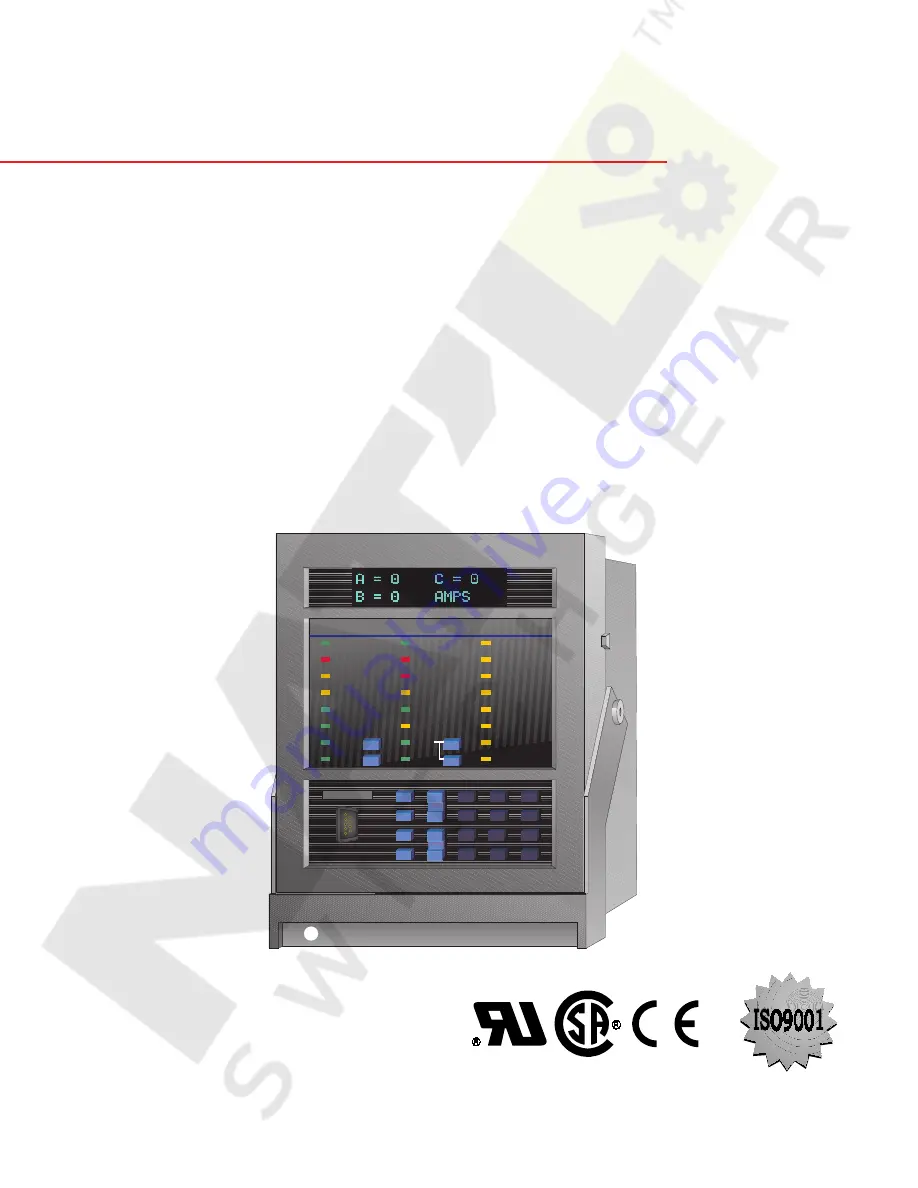
background image

R

E G

I S T E R

E D

750/760

FEEDER MANAGEMENT RELAY

®

Instruction Manual

Firmware Rev.: 402-000

Analog Rev.: 27H402A4.000

Control Rev.: 27H402C4.000

Manual P/N: 1601-0044-AL (GEK-106293A)

Copyright © 2002 GE Power Management

GE Power Management

215 Anderson Avenue, Markham, Ontario 

Canada L6E 1B3

Tel: (905) 294-6222   Fax: (905) 294-8512

Internet: http://www.GEindustrial.com/pm

Manufactured under an

ISO9001 Registered system.

g

GE Power Management

760

Feeder Management

®

818789A3.CDR

RELAY IN SERVICE

760 STATUS

SYSTEM STATUS

OUTPUT STATUS

BREAKER OPEN

1 TRIP

TRIP

BREAKER CLOSED

2 CLOSE

ALARM

RECLOSURE

ENABLED

3 AUXILIARY

PICKUP

RECLOSURE

DISABLED

4 AUXILIARY

SETPOINT

GROUP 1
SETPOINT

GROUP 2
SETPOINT

GROUP 3
SETPOINT

GROUP 4

RECLOSURE

IN PROGRESS

5 AUXILIARY

RESET

OPEN

NEXT

SETPOINT

MESSAGE

VALUE

ACTUAL

CLEAR

STORE

CLOSE

RECLOSURE

LOCKOUT

6 AUXILIARY

LOCAL

7 AUXILIARY

8

PROGRAM PORT

PROGRAM PORT

REMOTE

BREAKER

SELF-TEST

WARNING

7

8

9

4

5

6

1

2

0

3

HELP

.

g

Summary of Contents for 750

Page 1: ...nder an ISO9001 Registered system g GE Power Management 760 Feeder Management 818789A3 CDR RELAY IN SERVICE 760 STATUS SYSTEM STATUS OUTPUT STATUS BREAKER OPEN 1 TRIP TRIP BREAKER CLOSED 2 CLOSE ALARM RECLOSURE ENABLED 3 AUXILIARY PICKUP RECLOSURE DISABLED 4 AUXILIARY SETPOINT GROUP 1 SETPOINT GROUP 2 SETPOINT GROUP 3 SETPOINT GROUP 4 RECLOSURE IN PROGRESS 5 AUXILIARY RESET OPEN NEXT SETPOINT MESS...

Page 2: ......

Page 3: ...ce Should further information be desired or should particular problems arise which are not covered sufficiently for the purchaser s purpose the matter should be referred to the General Electric Company To the extent required the products described herein meet applicable ANSI IEEE and NEMA standards but no such assurance is given with respect to local codes and ordinances because they vary greatly ...

Page 4: ......

Page 5: ...ACKING 1 16 1 3 4 PHASORS TRANSIENTS AND HARMONICS 1 16 1 3 5 PROTECTION ELEMENTS 1 17 1 3 6 LOGIC INPUTS 1 17 2 GETTING STARTED 2 1 USING THE FRONT PANEL DISPLAY 2 1 1 DESCRIPTION 2 1 2 2 CHANGING SETPOINTS 2 2 1 DESCRIPTION 2 3 2 2 2 INSTALLING THE SETPOINT ACCESS JUMPER 2 3 2 2 3 HELP KEY 2 3 2 2 4 NUMERICAL SETPOINTS 2 3 2 2 5 ENUMERATION SETPOINTS 2 3 2 2 6 OUTPUT RELAY SETPOINTS 2 4 2 2 7 TE...

Page 6: ... CT INSTALLATION 3 11 3 2 9 AC VOLTAGE TRANSFORMER INPUTS 3 11 3 2 10 CONTROL POWER 3 12 3 2 11 TRIP CLOSE COIL SUPERVISION 3 13 3 2 12 SOLID STATE TRIP OUTPUT 3 14 3 2 13 LOGIC INPUTS 3 14 3 2 14 ANALOG INPUT 3 14 3 2 15 ANALOG OUTPUTS 3 15 3 2 16 RS485 RS422 COMMUNICATION PORTS 3 16 3 2 17 RS232 FRONT PANEL PROGRAM PORT 3 18 3 2 18 IRIG B 3 18 4 750 760 PC PROGRAM 4 1 OVERVIEW 4 1 1 DESCRIPTION ...

Page 7: ... 6 1 1 DESCRIPTION 6 1 6 2 A1 STATUS 6 2 1 DESCRIPTION 6 4 6 2 2 VIRTUAL INPUTS 6 4 6 2 3 HARDWARE INPUTS 6 4 6 2 4 LAST TRIP DATA 6 5 6 2 5 FAULT LOCATIONS 6 6 6 2 6 CLOCK 6 6 6 2 7 AUTORECLOSE 760 ONLY 6 7 6 3 A2 METERING 6 3 1 DESCRIPTION 6 8 6 3 2 CURRENT 6 8 6 3 3 VOLTAGE 6 9 6 3 4 FREQUENCY 6 10 6 3 5 SYNCHRONIZING VOLTAGE 6 10 6 3 6 POWER 6 11 6 3 7 ENERGY 6 13 6 3 8 DEMAND 6 14 a PHASE A C...

Page 8: ...SCODE SECURITY 7 3 7 4 COMMON SETPOINTS 7 4 1 DESCRIPTION 7 4 7 5 LOGIC DIAGRAMS 7 5 1 DESCRIPTION 7 6 7 5 2 SETPOINTS 7 6 7 5 3 MEASUREMENT UNITS 7 6 7 5 4 TIME DELAYS 7 6 7 5 5 LED INDICATORS 7 6 7 5 6 LOGIC 7 6 7 5 7 CONDITIONS 7 6 8 S1 RELAY SETUP 8 1 PASSCODE 8 1 1 DESCRIPTION 8 1 8 1 2 SETTINGS 8 1 8 2 COMMUNICATIONS 8 2 1 DESCRIPTION 8 2 8 2 2 SETTINGS 8 2 8 3 DNP COMMUNICATIONS 8 3 1 DESCR...

Page 9: ...TION 8 12 1 WARNING 8 13 8 12 2 SETTINGS 8 13 9 S2 SYSTEM SETUP 9 1 CURRENT SENSING 9 1 1 DESCRIPTION 9 1 9 1 2 SETTINGS 9 1 9 2 BUS VT SENSING 9 2 1 DESCRIPTION 9 2 9 2 2 SETTINGS 9 2 9 3 LINE VT SENSING 9 3 1 DESCRIPTION 9 3 9 3 2 SETTINGS 9 3 9 4 POWER SYSTEM 9 4 1 SETTINGS 9 4 9 5 FLEXCURVES 9 5 1 DESCRIPTION 9 5 9 5 2 SETTINGS 9 5 10 S3 LOGIC INPUTS 10 1 OVERVIEW 10 1 1 INTRODUCTION 10 1 10 2...

Page 10: ...ION 11 2 11 2 2 SETTINGS 11 2 11 3 OUTPUT RELAYS 3 7 AUXILIARY 11 3 1 DESCRIPTION 11 5 11 3 2 SETTINGS 11 5 12 S5 PROTECTION 12 1 TIME OVERCURRENT CURVE CHARACTERISTICS 12 1 1 DESCRIPTION 12 1 12 1 2 DEFINITE TIME CURVE 12 2 12 1 3 ANSI CURVES 12 3 12 1 4 IAC CURVES 12 4 12 1 5 IEC CURVES 12 5 12 2 DIRECTIONAL OVERCURRENT CHARACTERISTICS 12 2 1 DESCRIPTION 12 6 12 2 2 PHASE OVERCURRENT 12 7 12 2 3...

Page 11: ...VE SEQUENCE INSTANTANEOUS OVERCURRENT 12 43 12 6 4 NEGATIVE SEQUENCE DIRECTIONAL 12 45 12 6 5 NEGATIVE SEQUENCE VOLTAGE 12 47 12 7 VOLTAGE 12 7 1 DESCRIPTION 12 49 12 7 2 BUS UNDERVOLTAGE 12 49 12 7 3 UNDERVOLTAGE INVERSE TIME DELAY CHARACTERISTICS 12 50 12 7 4 LINE UNDERVOLTAGE 12 52 12 7 5 OVERVOLTAGE 12 54 12 7 6 NEUTRAL DISPLACEMENT 12 56 12 8 FREQUENCY 12 8 1 DESCRIPTION 12 58 12 8 2 UNDERFRE...

Page 12: ...14 S7 CONTROL 14 1 SETPOINT GROUPS 14 1 1 DESCRIPTION 14 1 14 1 2 SETPOINTS 14 2 14 2 SYNCHROCHECK 14 2 1 DESCRIPTION 14 6 14 2 2 SETPOINTS 14 6 14 3 MANUAL CLOSE BLOCKING 14 3 1 DESCRIPTION SETPOINTS 14 9 14 4 COLD LOAD PICKUP BLOCKING 14 4 1 DESCRIPTION 14 11 14 4 2 SETPOINTS 14 11 14 5 UNDERVOLTAGE RESTORATION 14 5 1 DESCRIPTION 14 14 14 5 2 SETPOINTS 14 14 14 6 UNDERFREQUENCY RESTORATION 14 6 ...

Page 13: ...ION 16 2 16 3 MODBUS PROTOCOL 16 3 1 DESCRIPTION 16 3 16 3 2 DATA LINK LAYER 16 3 16 3 3 CRC 16 ALGORITHM 16 4 16 3 4 SUPPORTED FUNCTION CODES 16 5 16 3 5 FUNCTION CODE 01H 02H READ BINARY STATUS 16 6 16 3 6 FUNCTION CODE 03H 04H READ ACTUAL VALUES SETPOINTS 16 7 16 3 7 FUNCTION CODE 05H EXECUTE OPERATION 16 8 16 3 8 FUNCTION CODE 06H STORE SINGLE SETPOINT 16 10 16 3 9 FUNCTION CODE 10H STORE MULT...

Page 14: ... 17 6 2 MEASUREMENT OF INPUT VOLTAGE 17 13 a BUS VOLTAGE 17 13 b BUS VOLTAGE FREQUENCY 17 14 c SYNCHRO VOLTAGE AND SYNCHRO FREQUENCY 17 14 17 6 3 MEASUREMENT OF REAL POWER WATTHOURS 17 15 17 6 4 MEASUREMENT OF REACTIVE POWER VARHOURS 17 15 17 6 5 MEASUREMENT OF APPARENT POWER 17 16 17 6 6 MEASUREMENT OF POWER FACTOR 17 16 17 6 7 MEASUREMENT OF CURRENT DEMAND 17 17 17 6 8 MEASUREMENT OF REAL POWER ...

Page 15: ...LTA VTs 17 36 17 7 24 LINE UNDERVOLT 3 4 17 36 17 7 25 OVERVOLTAGE 1 2 17 37 a FOR WYE VTs 17 37 b FOR DELTA VTs 17 37 c FOR WYE and DELTA VTs 17 38 17 7 26 NEUTRAL DISPLACEMENT WYE VTs ONLY 17 38 17 7 27 UNDERFREQUENCY 1 2 17 39 17 7 28 FREQUENCY DECAY 17 41 17 7 29 BREAKER FAILURE 17 42 17 8 MONITORING 17 8 1 PHASE CURRENT LEVEL 17 43 17 8 2 NEUTRAL CURRENT LEVEL 17 43 17 8 3 FAULT LOCATOR 17 44...

Page 16: ...BY UNDERVOLTAGE ON SOURCE 1 17 67 h MANUAL RESTORATION OF INCOMER 1 17 68 i TRANSFER INITIATED BY UNDERVOLTAGE ON SOURCE 2 17 68 j MANUAL RESTORATION OF INCOMER 2 17 68 k SIMULTANEOUS LOSS OF BOTH SOURCES 17 68 l AFTER PARALLEL TRIPPING OF SELECTED INCOMER 17 69 m TRANSFER BLOCKED BY OVERCURRENT ON INCOMER 1 17 69 n TRANSFER BLOCKED BY OVERCURRENT ON INCOMER 2 17 69 17 9 8 AUTORECLOSE 760 ONLY 17 ...

Page 17: ... quickly set points are set to typical default values and advanced features are disabled These settings can be repro grammed at any time Programming can be accomplished with the front panel keys and display Due to the numerous settings this manual method can be somewhat laborious To simplify programming and to provide a more intuitive interface programming can be accomplished with a personal compu...

Page 18: ...AC Currents 4 AC Voltages 20 Programmable Logic Inputs 14 contact and or virtual 6 virtual 1 Analog Input OUTPUTS 8 Electro Mechanical Relays 1 Solid State Trip 8 Analog Transducers MONITORING Phase and Neutral Current Level Power Factor Two Independent Stages Fault Locator Demand Ia Ib Ic MW Mvar MVA Analog Input Two Threshold Stages Two Rate Stages Overfrequency Trip Counter Limit Total Breaker ...

Page 19: ... Tripping Transfer Automatic Reclosing 760 Only Up To 4 Shots With Protection Modification and Current Supervi sion and Zone Coordination Breaker Open Close OTHER Data Logger 8 Channels Event Recorder 128 Events Waveform Capture 16 Samples Per Cycle Real Time Clock IRIG B Time Synchronization USER INTERFACE 40 Character Vacuum Fluorescent Display LED Indicators On Faceplate Clear English Language ...

Page 20: ...1 4 750 760 Feeder Management Relay GE Power Management 1 1 INTRODUCTION 1 PRODUCT OVERVIEW 1 Figure 1 1 PROTECTION ONE LINE DIAGRAM ...

Page 21: ...ed in Section 1 2 TECHNICAL SPECIFICATIONS of this chapter The remainder of this manual should be read and kept for reference to ensure maximum benefit from the 750 and 760 For further information please consult your local sales representative or the factory Comments about new features or modifications for your specific requirements are welcome NORTH AMERICA 1 800 547 3629 CANADA 905 294 6222 EURO...

Page 22: ...A G5 5A S1 1A S5 5A 25 60 Vdc 20 48 Vac 48 62 Hz 88 300 Vdc 70 265 Vac 48 62 Hz eight 0 1 mA Analog Outputs eight 0 5 mA Analog Outputs eight 0 10 mA Analog Outputs eight 4 20 mA Analog Outputs R red G green LO HI A1 A5 A10 A20 OTHER ACCESSORIES DEMO Metal carry case in which 750 760 unit may be mounted SR 19 1 PANEL Single cutout 19 panel SR 19 2 PANEL Dual cutout 19 panel RS 232 485 RS232 to RS4...

Page 23: ...t continuous 3 times rated current SENSITIVE GROUND CURRENT INPUT Source CT 1 to 50000 A primary 1 or 5 A secondary Relay Input 1 A or 5 A specified when ordering Burden Less than 0 2 VA at 1 or 5 A Conversion Range Low End 0 005 x CT Maximum 500 A primary fundamental frequency only Accuracy at 0 1 x CT 0 2 of 1 x CT at 0 1 x CT 1 of 1 x CT Overload Withstand 1 second 80 times rated current contin...

Page 24: ...or B N B C RMS Voltage Phasor C N C A RMS Voltage Phasor Accuracy 0 25 of full scale FREQUENCY A N A B Bus Line Voltage Range 16 to 90 Hz Accuracy 0 02 Hz SYMMETRICAL COMPONENTS Current Level Accuracy 1 5 of full scale Voltage Level Accuracy 0 75 of full scale Current Voltage Angle Accuracy 2 3Φ POWER FACTOR Range 0 00 Lag to 1 00 to 0 00 Lead Accuracy 0 02 3Φ REAL POWER Range 3000 0 to 3000 0 MW ...

Page 25: ...lation ship PHASE NEUTRAL GROUND NEGATIVE SEQUENCE INSTANTANEOUS OVERCURRENT PROTECTION Pickup Level 0 05 to 20 00 in steps of 0 01 x CT Dropout Level 97 to 98 of Pickup Time Delay 0 00 to 600 00 in steps of 0 01s Level Accuracy Per phase neutral ground current input I2 is 3 x phase input error Timing Accuracy at 0 ms time delay no intentional delay relay contacts 50 ms max solid state output 45 m...

Page 26: ... phases have to operate for output Level Accuracy Per voltage input Timing Accuracy 100 ms NEGATIVE SEQUENCE VOLTAGE Pickup Level 0 00 to 1 25 in steps of 0 01 x VT Dropout Level 97 to 98 of Pickup Time Delay 0 0 to 6000 0 in steps of 0 1 definite or inverse time Level Accuracy 3 x voltage input error Timing Accuracy 100 ms UNDERFREQUENCY 1 2 Minimum Voltage 0 00 to 1 25 in steps of 0 01 x VT in P...

Page 27: ...steps of 0 01 Hz Dropout Level Pickup 0 03 Hz Time Delay 0 0 to 6000 0 in steps of 0 1 s Level Accuracy 0 02 Hz Timing Accuracy at 60 Hz 34 ms at 50 Hz 40 ms FAULT LOCATOR Range 327 68 to 327 66 km miles 0 to 65534 Ohms Memory stores the 10 most recent faults DEMAND accuracies based on less than 2 x CT and 50 to 130 V inputs Measured Values Phase A B C Current A 3Φ Real Power MW 3Φ Reactive Power ...

Page 28: ...cy 1 or 2 Minimum Voltage Level 0 00 to 1 25 x VT in steps of 0 01 Minimum Frequency Level 20 00 to 60 00 in steps of 0 01 Hz Time Delay 0 1 to 100 0 in steps of 0 1 s Incomplete Sequence Time 1 to 10000 in steps of 1 min Level Accuracy Per voltage and frequency input Timing Accuracy 100 ms MANUAL CLOSE FEATURE BLOCKING Set to operate by a manual close command Programmable to block instantaneous o...

Page 29: ... WAVEFORM CAPTURE Data Channels 4 currents 3 voltages 14 logic input states and 8 output relays Sample Rate 16 per cycle Trigger Source Element pickup trip dropout control alarm event logic input or manual command Trigger Position 0 to 100 Storage capacity 2 to 16 events with 2048 to 256 samples of data respectively DATA LOGGER Data Channels 8 channels same parameters as for analog outputs availab...

Page 30: ...ve AC 5000 VA inductive PF 0 4 3 7 AUXILIARY 8 SELF TEST WARNING Make 30 A per ANSI IEEE C37 90 Carry 5 A continuous Break DC 150 W resistive DC 90 W inductive L R 40 ms AC 1250 VA resistive AC 500 VA inductive PF 0 4 Contact Durability 100 000 operations at 1800 opera tions hour at Rated Load 1 2 9 COMMUNICATIONS ALL PORTS 300 19200 baud programmable parity Modbus RTU or DNP 3 0 protocol EEPROM 1...

Page 31: ...EEE C37 90 40 x rated Amp for 2 sec 80 x Ir for 1 sec RFI Per Ontario Hydro 150 450 MHz 5 W transmit ter 25 cm and 50 MHz 15 W mobile transmitter 25 cm EMI Per ANSI IEEE C37 90 2 Electro magnetic Interference 150 MHz and 450 MHz 10V m Static Per IEC 801 2 Static Discharge Stress Vibration Per IEC 68 2 6 and IEC 255 21 1 PRODUCTION TESTS Thermal Cycling Operational test at ambient reduc ing to 40 C...

Page 32: ...mples are calibrated in software and then placed into the waveform capture buffer thus emulat ing a fault recorder The waveforms can be retrieved from the relay via the 750 760 PC Program for display and diagnostics 1 3 3 FREQUENCY TRACKING Frequency measurement is done by measuring the time between zero crossings of the BUS VT A and LINE VT voltage inputs Both signals are passed through a 72 Hz l...

Page 33: ...ental frequency only all harmonic components are removed Further explana tion of the FFT is beyond the scope of this document but can be found in any text on signal analysis All subsequent calculations e g RMS power demand etc are based upon the current and voltage phasors so the resulting values do not have any harmonic components either 1 3 5 PROTECTION ELEMENTS All protection elements are proce...

Page 34: ...1 18 750 760 Feeder Management Relay GE Power Management 1 3 THEORY OF OPERATION 1 PRODUCT OVERVIEW 1 Figure 1 3 HARDWARE BLOCK DIAGRAM ...

Page 35: ...l through all the available setpoint page headers n CURRENT n ENTER for more Press the key until the page A2 METERING appears Now press the key and the first sub page heading for page 2 of actual values appears Pressing the and keys will scroll the display up and down through the sub page headers n DEMAND n ENTER for more Press the key until the DEMAND sub page heading appears Press to display the...

Page 36: ...manual by using a path The example shown in the figure gives the key presses required to reach the point given by the path A3 MAINTENANCE ARCING CURRENT TOTAL ARCING CURRENT B Figure 2 1 PANEL KEYING EXAMPLE n ACTUAL VALUES n A1 STATUS n ACTUAL VALUES n A2 METERING n ACTUAL VALUES n A3 MAINTENANCE MESSAGE n TRIP COUNTERS n ENTER for more MESSAGE n ARCING CURRENT n ENTER for more TOTAL ARCING CURRE...

Page 37: ...nt Two methods of editing and storing a numerical setpoint value are available The 750 760 numeric keypad works the same as any electronic calculator A number is entered one digit at a time with the 0 to 9 and decimal keys The leftmost digit is entered first and the rightmost digit is entered last Pressing the key before the key returns the original value to the display The key increments the disp...

Page 38: ...ASE TIME O C 1 RELAYS 3 7 3 If an application requires the PHASE TIME O C 1 protection element to operate output relay 3 AUXILIARY select this output relay by pressing the 3 key n NEW SETPOINT n HAS BEEN STORED Press the key to store this change into memory As before confirma tion of this action will momentarily flash on the display USER INPUT A NAME User Input A Move to message S3 LOGIC INPUTS US...

Page 39: ...station Monitor No data communications to other equipment INSTRUMENT TRANSFORMER DATA Bus VTs 3 x Wye connected ratio 14 4 kV 120 V Phase CTs 3 x Wye connected ratio 600 5 Amp PHASE PROTECTION SETTINGS Time O C 1 curve shape Moderately Inverse pickup 840 A multiplier 20 2 Instantaneous O C 1 pickup 840 A phases required Any Two delay 0 s Instantaneous O C 2 pickup 10100 A phases required Any Two d...

Page 40: ... Remote Open INPUT 4 ASSERTED LOGIC Contact Close INPUT 5 NAME Remote Close INPUT 5 ASSERTED LOGIC Contact Close INPUT 6 NAME Reset INPUT 6 ASSERTED LOGIC Contact Close S3 LOGIC INPUTS CONTROL FUNCTIONS LOCAL MODE Input 3 RESET Input 6 REMOTE OPEN Input 4 REMOTE CLOSE Input 5 c ALARM AFTER DELAY INPUT S3 LOGIC INPUTS USER INPUT A USER INPUT A NAME Substation Monitor USER INPUT A SOURCE Input 1 USE...

Page 41: ...T 120A pickup 600A pri NEUTRAL TIME OC 1 CURVE Mod Inverse NEUTRAL TIME OC 1 MULTIPLIER 10 00 NEUTRAL TIME OC 1 RESET Instantaneous e NEUTRAL INSTANTANEOUS O C 1 S5 PROTECTION NEUTRAL CURRENT NEUTRAL INST OC 1 NEUTRAL INST OC 1 FUNCTION Trip NEUTRAL INST OC 1 PICKUP 0 20 x CT 120A pickup 600A pri NEUTRAL INST OC 1 DELAY 0 00 s f NEUTRAL INSTANTANEOUS O C 2 S5 PROTECTION NEUTRAL CURRENT NEUTRAL INS...

Page 42: ...intended application If this warning is ignored protection is active and will be using factory default setpoints The RELAY IN SERVICE indicator will be on n SELF TEST WARNING n Relay Not Ready This diagnostic message indicates that the relay is in the Not Ready state 760 OPERATION Not Ready Move to the message S1 RELAY SETUP INSTALLATION 760 OPERATION To put the relay in the Ready state press the ...

Page 43: ...g to allow the safe removal of the relay from an energized panel There are no electronic components in the case Figure 3 1 CASE DIMENSIONS To prevent unauthorized removal of the drawout relay a wire lead seal can be installed through the slot pro vided in the middle of the locking latch With this seal in place the relay cannot be removed from the case Even though a passcode or setpoint access jump...

Page 44: ...jacent equipment Figure 3 3 SINGLE AND DOUBLE UNIT PANEL CUTOUTS Before mounting the SR unit in the supporting panel remove the unit from the case From the front of the panel slide the empty case into the cutout To ensure the case s front bezel sits flush with the panel apply pressure to the bezel s front while bending the retaining tabs 90 degrees These tabs are located on the sides and bottom of...

Page 45: ...l result in damage to the relay and case To remove the unit from the case 1 Open the door by pulling from the top or bottom of its right side It will rotate to the left about its hinges 2 Press upward on the locking latch which is located below the handle and hold in its raised position The tip of a small screwdriver may prove helpful in this operation Figure 3 5 PRESS LATCH UP AND PULL HANDLE 3 W...

Page 46: ...t of the case and align the rolling guide pins near the hinges of the relay s handle with the case s guide slots 4 Slide the unit into the case until the guide pins on the unit have engaged the guide slots on either side of the case 5 Once fully inserted grasp the handle from its center and rotate it down from the raised position towards the bottom of the relay 6 Once the unit is fully inserted th...

Page 47: ...the important aspects of interconnections in the general areas of instrument transformer inputs other inputs outputs communications and grounding Figure 3 8 REAR TERMINAL LAYOUT below shows the rear terminal layout of the 750 760 Relay contacts must be considered unsafe to touch when system is energized If the cus tomer requires the relay contacts for low voltage accessible applications it is thei...

Page 48: ... COM B7 COM2 RS485 F7 5 AUXILIARY RELAY COM B8 COM2 RS485 COM F8 6 AUXILIARY RELAY NO B9 SHIELD GROUND F9 6 AUXILIARY RELAY COM B10 IRIG B F10 7 AUXILIARY RELAY COM B11 IRIG B F11 8 SELF TEST WARNING RELAY NO B12 RESERVED F12 8 SELF TEST WARNG RELAY COM LOGIC INPUTS CT and VT INPUTS GROUND C1 LOGIC INPUT 1 G1 COIL MONITOR 1 C2 LOGIC INPUT 2 G2 COIL MONITOR 2 C3 LOGIC INPUT 3 G3 SENSITIVE GROUND CT...

Page 49: ...GE Power Management 750 760 Feeder Management Relay 3 7 3 INSTALLATION 3 2 TYPICAL WIRING 3 3 2 3 TYPICAL WIRING DIAGRAM Figure 3 9 TYPICAL WIRING DIAGRAM ...

Page 50: ...ensi tive Ground Current inputs Before making ground connections consider that the relay automatically calcu lates the neutral residual current from the sum of the three phase current phasors The following figures show three possible ground connections using the ground current input terminals G10 H10 and three possible sen sitive ground connections using the sensitive ground current input terminal...

Page 51: ...GE Power Management 750 760 Feeder Management Relay 3 9 3 INSTALLATION 3 2 TYPICAL WIRING 3 Figure 3 10 GROUND INPUTS Figure 3 11 SENSITIVE GROUND INPUTS ...

Page 52: ...ar the transformer neutral The Sensitive Ground input terminals G3 H3 can be used Although the 750 760 is designed for feeder protection it can provide Restricted Earth Fault protec tion on transformers that do not have dedicated protection To use the 750 760 for this type of protec tion a stabilizing resistor and possibly a non linear resistor will be required For more details see Section 12 5 6 ...

Page 53: ...SFORMER INPUTS The 750 and 760 have four channels for AC voltage inputs each with an isolating transformer Voltage trans formers up to a maximum 5000 1 ratio may be used The nominal secondary voltage must be in the 50 to 240 V range The three phase inputs are designated as the bus voltage The bus VT connections most commonly used wye and delta or open delta are shown in the typical wiring diagram ...

Page 54: ...power supplied to the relay must match the installed power supply range If the applied voltage does not match damage to the unit may occur All grounds MUST be con nected for normal operation regardless of control power supply type The label found on the left side of the relay specifies its order code or model number The installed power supply s operating range will be one of the following LO 20 to...

Page 55: ...it to be monitored when the breaker is closed and a close circuit to be monitored when the breaker is open Circuit breakers equipped with standard control circuits have a 52a auxiliary contact which only allows tripping of the breaker when it is closed In this breaker state the 52a contact is closed and a trickle current will flow through the trip circuitry When the breaker is open the 52a auxilia...

Page 56: ...d to terminal C12 This is the 32 VDC voltage rail The other side of the dry contact is connected to the required logic input terminal When a dry contact closes a current of approxi mately 2 mA will flow through the associated circuit A wet contact has one side connected to the positive terminal of an external DC power supply The other side of this contact is connected to the required logic input t...

Page 57: ...utput signals are internally isolated and allow connection to devices which sit at a different ground potential Each analog output terminal is clamped to within 36 volts of ground To minimize the affect of noise external connections should be made with shielded cable and only one end of the shield should be grounded If a voltage output is required a burden resistor must be connected at the input o...

Page 58: ...nimize errors from noise the use of shielded twisted pair wire is recommended Correct polarity should also be observed For instance SR type relays must be connected with all B1 terminals labeled COM1 RS485 connected together and all B2 terminals labeled COM1 RS485 connected together Terminal B3 COM1 RS485 COM should be connected to the common wire inside the shield To avoid loop currents the shiel...

Page 59: ...GE Power Management 750 760 Feeder Management Relay 3 17 3 INSTALLATION 3 2 TYPICAL WIRING 3 Figure 3 20 RS422 CONNECTION ...

Page 60: ... is a standard time code format that allows time stamping of events to be synchronized among con nected devices within 1 millisecond The IRIG time code formats are serial width modulated codes which can be either DC level shift or amplitude modulated AM form Third party equipment is available for generating the IRIG B signal this equipment may use a GPS satellite system to obtain the time referenc...

Page 61: ...PC program to slow down Processor minimum 486 Pentium recommended Memory minimum 4 Mb 16 Mb recommended minimum 540 K of conventional memory Hard Drive 20 Mb free space required before installation of PC program O S Windows 3 1 Windows 3 11 for Workgroups Windows 95 Windows NT ADDITIONAL WINDOWS 3 1 3 11 CONSIDERATIONS Installation of SHARE EXE required Close other applications spreadsheet or word...

Page 62: ...tallation disks or the GE Power Management CD ROM To deter mine the most recent version visit the GE Power Management website at www GEindustrial com pm 2 Run 750 760 PC Program 3 Select the Help About 750PC menu item 4 Compare the PC Program version shown in the About 750PC dialog box with the version shown on the CD ROM or website If it is higher or does not suppose the revision of firmware that...

Page 63: ... 2 GE POWER MANAGEMENT WELCOME SCREEN 3 Select the Products Software menu item 4 Select either the 750 or 760 from the list of products Both links lead to the same software selection 5 Follow the on screen instructions to complete the installation of the PC Program The Typical installation will include the PC Program and the relay firmware files The 750 760 PC Program installs the relay firmware f...

Page 64: ...e current setpoints or setpoint file Properties Selects the properties for the setpoint file Send Info to Relay Sends the setpoint file to the relay Print Setup Selects content and format of output Print Preview Displays full pages as they will be printed Print Print setpoints or setpoint file The Setpoint menu contains the same setpoint pages as seen in the relay This provides a means to view and...

Page 65: ...e computer communication parameters Modem Allows a phone number to be dialed using a modem Troubleshooting Inspect Insert data into the memory map using MOD BUS address Update Firmware Update the relay firmware The Help menu contains Instruction Manual View and search the 750 760 Product Instruction Manual Using Help Displays Instructions about using Help About 750PC Displays the latest software v...

Page 66: ...me as S1 RELAY SETUP COMMUNICATIONS SLAVE ADDRESS Communication Port This setting should be the COM port on your computer that is connected to the 750 760 i e COM1 or COM2 On most PCs COM1 is used by the mouse device and so COM2 is usually available for communications Baud Rate This setting should be the same as S1 RELAY SETUP COMMUNICATIONS BAUD RATE Parity This setting should be the same as S1 R...

Page 67: ... From the Communications menu select Update Firmware Note that units that do not have a bootware revision 3 00 or newer must be set to a baud rate of 9600 and a slave address of 1 before downloading new firmware Check the bootware revision of the relay shown on page A5 Revision Codes 2 The following warning message will pop up Click on the Yes button to proceed or No to abort Figure 4 6 UPGRADE RE...

Page 68: ...wing example illustrates entering setpoints for S2 SYSTEM SETUP POWER SYSTEM using the 750 760 PC Program 1 From the Setpoint menu select System Setup 2 From the System Setup window select the Sensing tab Figure 4 8 S2 SETPOINTS ENTRY DIALOG BOX For setpoints requiring numerical values i e Nominal Frequency click the mouse anywhere inside the setpoint box This displays a numerical keypad showing t...

Page 69: ...display box will be shown displaying the voltage actual values Figure 4 9 A2 METERING DIALOG BOX 4 4 5 SAVING SETPOINTS TO A FILE Saving setpoints to a file on your PC is accomplished as follows 1 If the 750 760PC software is not connected to a relay select Properties from the File menu The dialog box shown below will appear allowing you to configure the software to match the options of a particul...

Page 70: ...ram will then read all the relay setpoint values and store them to the selected file 4 4 6 LOADING SETPOINTS FROM A FILE The following steps show how to download a setpoint file to a relay 1 From the File menu select Open 2 The following dialog box will pop up The program will display all filenames with the extension 750 for 750 file type and 760 for 760 file type Select the file name of the setpo...

Page 71: ... stored by the relay Data is captured for analog current and voltage inputs Ia Ib Ic Ig Isg Va Vb Vc Vs as well as digital data for the output relays and the contact inputs states To use the Waveform Capture function run the 750 760 PC Program and establish communications with a connected 750 760 relay Select Actual Waveform Capture from the main window to open the Waveform Capture window The win ...

Page 72: ...ing Group and Spline as desired Select the same Scaling Group for all parameters to be scaled together Using Spline will result in a smoothing of the wave form Figure 4 14 GRAPH ATTRIBUTES DIALOG BOX 4 4 9 DATA LOGGER The data logger feature is used to sample and record up to eight actual values at an interval that is defined by the user Refer to Section 8 7 DATA LOGGER on page 8 7 for more detail...

Page 73: ...ogram port is also provided for connection with a computer running the 750 760 PC program The 40 character vacuum fluorescent display provides English messages that are visible under varied lighting conditions While the keypad and display are not being used the screen will display system information by scrolling through a maximum of 30 user selected default messages These default messages will onl...

Page 74: ...ondition clears the indicator remains illuminated and can be turned off with a reset PICKUP For the purpose of testing and calibration verification this indicator will light steady when any protec tion feature has its pickup threshold exceeded Eventually if the fault condition persists a trip will be issued by the relay If the measured parameter drops below its pickup level the indicator will turn...

Page 75: ...ORS The 750 and 760 have eight output relays 1 TRIP 2 CLOSE and 8 SELF TEST WARNING have fixed opera tion while 3 7 AUXILIARY are configurable Regardless of the mode of operation the corresponding front panel indicator turns on while the output relay is signaling If the non operated state of an output relay is pro grammed as de energized the corresponding indicator will be on when the normally ope...

Page 76: ...o be entered through the numeric keypad The key may be pressed at any time to display a list of context sensitive help messages Continue to press the key to display all the help messages and return to the original display The key will reset any latched conditions that are not presently active This includes resetting latched output relays latched TRIP indicators breaker operation failure and trip c...

Page 77: ...n of the power system Major problems indicate a very serious problem with the relay which comprises all aspects of relay operation SELF TEST WARNINGS MAY INDICATE A SERIOUS PROBLEM WITH THE RELAY HARDWARE Upon detection of either a minor or major problem the relay will De energize the 8 SELF TEST WARNING relay Indicate the failure in the diagnostic message queue Record the failure in the EVENT REC...

Page 78: ...ecking code Any function of the relay is susceptible to malfunction from this failure Force Analog Out Minor Occurs when the setpoint FORCE ANALOG OUTPUTS FUNCTION is set to Enabled Force Relays Minor Occurs when the setpoint FORCE OUTPUT RELAYS FUNCTION is set to Enabled Internal RS485 Minor Caused by a failure of the internal RS485 communication link Attempts to read Actual Values or write Setpo...

Page 79: ...n the subgroup S1 RELAY SETUP DEFAULT MESSAGES ENTER PASSCODE IS INVALID This flash message is displayed in response to an incorrectly entered pass code when attempting to enable or disable setpoint access ENTRY MISMATCH CODE NOT STORED This flash message is displayed while changing the programmed password from the command message S1 RELAY SETUP PASSCODE CHANGE PASS CODE If the passcode entered at...

Page 80: ...DEFAULT MESSAGES Pressing the key again while this message is displayed removes the default message from the list PRESSED KEY IS INVALID HERE This flash message is displayed in response to any pressed key that has no meaning in the current context RESETTING LATCHED CONDITIONS This flash message is displayed in response to the key All active latched conditions trips alarms or latched relays for whi...

Page 81: ...sing the keys and display 2 Front program port and a portable computer running the 750 760 PC program supplied with the relay 3 Rear RS485 RS422 COM 1 port or RS485 COM 2 port with a SCADA system running user written soft ware Table 6 1 ACTUAL VALUES MESSAGE SUMMARY ACTUAL VALUES A1 STATUS ACTUAL VALUES A2 METERING ACTUAL VALUES A3 MAINTENANCE VIRTUAL INPUTS CURRENT TRIP COUNTERS HARDWARE INPUTS V...

Page 82: ...6 2 750 760 Feeder Management Relay GE Power Management 6 1 OVERVIEW 6 ACTUAL VALUES 6 Figure 6 1 ACTUAL VALUES BLOCK DIAGRAM 1 OF 2 ...

Page 83: ...GE Power Management 750 760 Feeder Management Relay 6 3 6 ACTUAL VALUES 6 1 OVERVIEW 6 Figure 6 2 ACTUAL VALUES BLOCK DIAGRAM 2 OF 2 ...

Page 84: ...al condition selected as part of their asserted logic Refer to setpoint messages under S3 LOGIC INPUTS LOGIC INPUT SETUP Logic Input 1 Off Range On Off Displays and allows setting the state of virtual input 1 The Logic Input 1 dis play heading is user programmable Only active virtual inputs are displayed active virtual inputs are those that have their INPUT X ASSERTED LOGIC setpoint programmed to ...

Page 85: ...his message displays the values of the three phase currents at the moment of the event GROUND CURRENT 0 A This messages displays the value of the ground current measured via the ground current input at the moment of the event SENSTV GND CURRENT 0 00 A This message displays the value of the sensitive ground current measured via the sensitive ground current input at the moment of the event NEUTRAL C...

Page 86: ...t location 0 TYPE OF FAULT n a This message displays the type of fault as determined by the fault locator The message is displayed only if a fault location calculation has been performed DISTANCE TO FAULT 0 00 km This message displays the calculated distance to the fault as determined by the fault locator in the units selected The message can only be displayed if a fault location calculation has b...

Page 87: ... reclose system will be either reset or locked out The value displayed in this message is the value contained in the Shot Limit memory Each time a reclose shot is performed in a given sequence this Shot Limit is reduced by one The Shot Limit can also be reduced to any given value less than the programmed value by the current supervision function AUTORECLOSE SHOT RATE 0 hr The number of reclosures ...

Page 88: ...t 6 3 2 CURRENT Phase current magnitudes phasors and sequence components are displayed as shown below CURRENT ENTER for more The Current actual values path is ACTUAL VALUES A2 METERING CURRENT A 0 B 0 C 0 Amps Displays the RMS magnitudes of phase A B and C currents together in one message OF LOAD TO TRIP 0 Displays the ratio of highest phase current to lowest overcurrent pickup level AVERAGE CURRE...

Page 89: ...plays the RMS line voltage magnitudes together in one message AVERAGE LINE VOLTAGE 0 00 kV Displays the calculated average of the RMS line voltages AN 0 00 BN 0 00 CN 0 00 kVolts Displays the RMS phase voltage magnitudes together in one message AVERAGE PHASE VOLTAGE 0 00 kV Displays the calculated average of the RMS line voltages LINE A B VOLTAGE 0 00 kV 0 Lag Displays the measured A B RMS voltage...

Page 90: ...0 00 Hz Displays the frequency of the power system This is the frequency used for fre quency tracking as discussed in Section 1 3 3 FREQUENCY TRACKING on page 1 16 FREQUENCY DECAY RATE 0 00 Hz s Displays the frequency decay rate When the value is positive the frequency is decreasing when the value is negative the frequency is increasing SYNCHRO VOLTAGE ENTER for more The Synchronizing Voltage actu...

Page 91: ...r 1 1 MVA PN 10 MVA MW Mvar MVA MWhr Mvarh 0 01 10 MVA PN MW Mvar MVA MWhr Mvarh 0 1 POWER ENTER for more The Power actual values path is ACTUAL VALUES A2 METERING POWER 3Φ REAL POWER 0 0 MW This message displays the three phase real power 3Φ REACTIVE POWER 0 0 Mvar This message displays the three phase reactive power 3Φ APPARENT POWER 0 0 MVA This message displays the three phase apparent power 3...

Page 92: ...tt Var PF Lead Q Q Q Q Q Q Q Q Q1 Q2 Q3 Q4 P1 P2 P3 P4 S1 EI1 S2 EI2 S3 EI3 S4 EI4 P P P P P P P P 818773AC CDR Watt Var PF Lag Bus Voltage E S2 S1 S4 S3 4 4 POWER PLANE DIAGRAMS POSITIVE ROTATION PHASOR DIAGRAM Angle By Which Voltage Leads Current 4 Watt Var PF Lead ONE LINE DIAGRAM POSITIVE DIRECTION SOURCE LOAD RELAY PER IEEE DEFINITIONS Watt Var PF Lag ...

Page 93: ...ATTHOURS value POSTIVE WATTHOUR COST 0 This message displays the approximate cost of the positive watthours NEGATIVE WATTHOURS 0 0 MWh This message displays the negative watthours Real power in the negative direction will add to this accumulated value Real power opposite to this direc tion will add to the POSITIVE WATTHOURS value NEGATIVE WATTHOUR COST 0 This message displays the positive watthour...

Page 94: ...e similar to those for Phase A Current Demand b LAST RESET DATE DEMAND ENTER for more The Demand actual values path is ACTUAL VALUES A2 METERING DEMAND PHASE A CURRENT ENTER for more The Phase A Current Demand actual values path is ACTUAL VALUES A2 METERING DEMAND PHASE A CURRENT LAST PHASE A CURRENT DEMAND 0 A This message displays the phase A current demand over the most recent time interval MAX...

Page 95: ...nput as defined in S6 MONITORING ANALOG INPUT ANALOG INPUT SETUP In this actual values display the name programmed in setpoint message S6 MONITORING ANALOG INPUT ANALOG INPUT SETUP ANALOG INPUT NAME will be displayed instead of the fac tory default ANALOG INPUT The name of the units programmed in the set point message S6 MONITORING ANALOG INPUT ANALOG INPUT SETUP ANALOG INPUT UNITS will be display...

Page 96: ... TRIPS 0 The total number of breaker trips as detected by the 52a b contacts since the TRIP COUNTERS LAST RESET date GROUND OC TRIPS 0 The total number of ground overcurrent trips since the TRIP COUNTERS LAST RESET date SENSTV GND OC TRIPS 0 The total number of sensitive ground overcurrent trips since the TRIP COUNTERS LAST RESET date NEUTRAL OC TRIPS 0 The total number of neutral overcurrent trip...

Page 97: ...NT ΦA 0 kA2 cycle This message displays the total accumulated phase A arcing current in kA2 cycle since the ARCING CURRENT LAST RESET date TOTAL ARCING CURRENT ΦB 0 kA2 cycle This message displays the total accumulated phase B arcing current in kA2 cycle since the ARCING CURRENT LAST RESET date TOTAL ARCING CURRENT ΦC 0 kA2 cycle This message displays the total accumulated phase C arcing current i...

Page 98: ... is programmed to wye If the VT CONNECTION TYPE setpoint is programmed to delta line voltages A B B C and C A are dis played The following example shows the display messages for a single event E1234 Mar 16 1997 ENTER for more This is the heading message for a single event it displays the event number date and cause of the event that occurred To view more information regarding the event press the k...

Page 99: ... PHASE C N VOLTAGE 0 A 0 Lag Displays the C N voltage phasor at the moment of the event SYSTEM FREQUENCY 0 00 Hz Displays the value of the system frequency at the moment of the event SYNCHRO VOLTAGE 0 00 kV 0 Lag Displays the RMS voltage phasor of the line VT input at the moment of the event SYNCHRO FREQUENCY 0 00 Hz Displays the frequency of the line VT input at the moment of the event ANALOG INP...

Page 100: ...t Messages are shown below Cause General Events These are events that occur when a specific operation takes place PICKUP Φ Cause Pickup Events These are events that occur when a protection element picks up and starts timing TRIP Φ Cause Trip Events These are events that occur when an element whose function has been pro grammed to Trip or Trip AR operates ALARM Φ Cause Alarm Events These are events...

Page 101: ...d to L O Set Date Reset AR Shot Rate Autoreclose Reset Phase Time OC 1 Phase Dir Reverse Phase Current Level Analog Threshold 1 Phase Time OC 2 Neutral Dir Reverse Neutral Current Level Analog Threshold 2 Phase Inst OC 1 Neg Seq Dir Reverse Overfrequency Analog Rate 1 Phase Inst OC 2 Sens Gnd Dir Reverse Out of Sync Analog Rate 2 Ground Time OC Ground Dir Reverse Power Factor 1 Trip Counter Ground...

Page 102: ...q 1 Block Neutral Time OC 1 Xmfr Lockout Block Underfreq 2 Block Neutral Time OC 2 Source Trip Setpoint Group 2 Block Freq Decay Block Neutral Inst OC 1 Cls From Incomer 1 Setpoint Group 3 Block Neg Seq Volt Block Neutral Inst OC 2 Cls From Incomer 2 Setpoint Group 4 Block Restoration Block Neg Seq Inst Simulate Fault Trigger Data Log Block Trip Count Block Neg Seq Time Initiate Reclosure Trigger ...

Page 103: ...ssage displays the manufacturer s telephone and fax number Internet Address GEindustrial com pm This message displays the GE Power Management internet address REVISION CODES ENTER for more The Revision Codes actual values path is ACTUAL VALUES A5 PRODUCT INFO REVISION CODES GE Power Management 750 REVISION 4 00 This message displays the product name and software revision HARDWARE REVISION H This m...

Page 104: ...ON DATES ENTER for more The Calibration Dates actual values path is ACTUAL VALUES A5 PRODUCT INFO CALIBRATION DATES FACTORY CALIBRATION DATE Oct 25 1997 This message displays the date the relay was calibrated at the factory LAST CALIBRATION DATE Oct 25 1997 This message displays the date calibration parameters were last modified ...

Page 105: ...NS 2 CLOSE RELAY CLOCK LINE VT SENSING CONTROL FUNCTIONS 3 AUXILIARY EVENT RECORDER POWER SYSTEM USER INPUTS 4 AUXILIARY TRACE MEMORY FLEXCURVE A BLOCK FUNCTIONS 5 AUXILIARY DATA LOGGER FLEXCURVE B BLOCK OC FUNCTIONS 6 AUXILIARY FRONT PANEL TRANSFER FUNCTIONS 7 AUXILIARY DEFAULT MESSAGES RECLOSE FUNCTIONS USER TEXT MESSAGES MISC FUNCTIONS CLEAR DATA INSTALLATION SETPOINTS S5 PROTECTION SETPOINTS S...

Page 106: ...relay leaves the factory with setpoints programmed to default values and it is these values that are shown in all the setpoint message illustrations Many of these factory default values can be left unchanged At a minimum the setpoints in page S2 SYSTEM SETUP must be entered for the system to function cor rectly In order to safeguard against the installation of a relay whose setpoints have not been...

Page 107: ...d there are no restrictions via the communications ports When the passcode is programmed to any other value setpoint access is restricted for the front panel and all communications ports Access is not permitted until the passcode is entered via the keypad for the front panel or is programmed into a specific register via communications Note that enabling setpoint access on one interface does not au...

Page 108: ... Disabled the feature is not operational If Setting Enabled the feature is operational If Setting Trip the feature is operational When an output is generated the feature will declare a Trip condition which will operate the 1 TRIP relay and any other selected output relays and display the appropriate trip message If Setting Trip AR Overcurrent features of 760 Only the feature is opera tional When a...

Page 109: ...ction only as determined by the directional element If setting Reverse the element is allowed to operate for current flow in the reverse direction only as determined by the directional element PHASES REQUIRED FOR OPERATION Any One Range Any One Any Two All Three This setpoint is available for those features which measure each phase param eter individually If Setting Any One an output is generated ...

Page 110: ...y above Element operation of the detector is controlled by the signal entering the RUN inset The measurement comparison can only be performed if a logic 1 is provided at the RUN input Relationship between setpoint and input parameter is indicated by mathematical symbols less than greater than etc ANSI device number if one exists is indicated above the block 7 5 4 TIME DELAYS Shown as a block with ...

Page 111: ...ode is not 0 Select Yes and follow directions to restrict setpoint access ALLOW ACCESS TO SETPOINTS No Range Yes No This message is only displayed when setpoint access is restricted In this state new setpoints cannot be entered In order to regain setpoint access select Yes and follow directions to enter the passcode that was previously pro grammed If the passcode is correctly entered entering new ...

Page 112: ...ve a unique address COM1 RS485 422 BAUD RATE 9600 Range 300 1200 2400 4800 9600 19200 Select the baud rate for COM1 the RS485 RS422 communication port All relays on the communication link and the computer connecting them must run at the same baud rate The fastest response will be obtained at 19200 Baud Slower baud rates should be used if noise becomes a problem The data frame is fixed at 1 start 8...

Page 113: ...RM MODE Never Range Never Sometimes Always Select the data link confirmation mode desired for responses sent by the 750 760 When Sometimes is selected data link confirmation is only requested when the response contains more than one frame DATA LINK CONFIRM TIMEOUT 1000 ms Range 0 to 65000 in steps of 1 ms Select a desired timeout If no confirmation response is received within this time the 750 760...

Page 114: ... July 15 1998 would be entered as 07 15 1998 If entered from the front panel the new date will take effect the moment the key is pressed TIME HH MM SS 16 30 00 Range Hour 0 to 23 Minute 0 to 59 Second 0 to 59 Enter the current time by using two digits for the hour in 24 hour time two dig its for the minutes and two digits for the seconds If entered from the front panel the new time will take effec...

Page 115: ...er will not clear any data in the event recorder RECORD PICKUP EVENTS Enabled Range Enabled Disabled Enter Disabled for this setpoint to inhibit recording of element pickup events RECORD DROPOUT EVENTS Enabled Range Enabled Disabled Enter Disabled for this setpoint to inhibit recording of element dropout events RECORD TRIP EVENTS Enabled Range Enabled Disabled Enter Disabled for this setpoint to i...

Page 116: ...triggered than the allowable number of events selected by this setpoint the oldest data is discarded to make room for the new capture For example 4 x 1024 indicates that the last three events with 1024 data sam ples per channel 64 cycles can be stored in memory Note that one buffer must be reserved for capturing the next event Changing this setpoint will clear any data that is currently in memory ...

Page 117: ...ETUP DATA LOGGER SAMPLE RATE 1 cycle Range 1 cycle 1 second 1 min 5 min 10 min 15 min 20 min 30 min 60 min Select the time interval at which the actual value data will be recorded This setpoint multiplied by the number of samples to accumulate determines the duration of the data log record For example if the sample rate is 15 minutes and continuous mode is enabled then the duration of the data log...

Page 118: ...ed as an Analog Output Function Select the actual value that is to be recorded in channel 1 of the data log Note If all channel sources 1 through 8 are programmed to Disabled then the data logger will not collect data in continuous mode or respond to triggers in trigger mode CHANNEL 2 SOURCE Phase B Current Range Any Value that may be Assigned as an Analog Output Function Select the actual value t...

Page 119: ...estore the last message displayed on the screen DEFAULT MESSAGE INTENSITY 25 Range 25 to 100 in steps of 25 To extend the life of the phosphor in the vacuum fluorescent display the bright ness of the display can be attenuated when default messages are being dis played When interacting with the display using the front panel keys the display will always operate at full brightness DISPLAY FILTER CONS...

Page 120: ...ode 2 Select the Setpoint or Actual Value message to be entered as a default message so that it is displayed 3 Press the key followed by the key while the message is displayed The screen will display PRESS ENTER TO ADD AS DEFAULT Press the key again while this message is being dis played The message is now added to the default message list 8 9 4 REMOVING DEFAULT MESSAGES Default messages can be re...

Page 121: ...and keys to change the character A space is selected like a character 5 Press the key to store the character and advance the cursor to the next position To skip over a character press the key 6 Continue entering characters and spaces until the desired message is displayed If a character is entered incorrectly repeatedly press the key until the cursor returns to the position of the error and enter ...

Page 122: ... the current date upon issuing this command CLEAR MAX DEMAND DATA No Range Yes No Enter Yes to clear all maximum demand data values under the actual values subgroup A2 METERING DEMAND namely MAX PHASE A CURRENT DEMAND MAX PHASE B CURRENT DEMAND MAX PHASE C CURRENT DEMAND MAX REAL POWER DEMAND MAX REACTIVE POWER DEMAND and MAX APPARENT POWER DEMAND The DEMAND DATA LAST RESET date is updated to the ...

Page 123: ... to clear all accumulated trip counter values under the actual values subgroup A3 MAINTENANCE TRIP COUNTERS This command should be used on a new installation or after new equipment has been installed The TRIP COUNTERS LAST RESET date is updated to the current date upon issuing this command RESET ARCING CURRENT DATA No Range Yes No Enter Yes to clear all accumulated arcing current values under the ...

Page 124: ...8 14 750 760 Feeder Management Relay GE Power Management 8 12 INSTALLATION 8 S1 RELAY SETUP 8 ...

Page 125: ...ve ground input may be used In this case the sensitive ground CT pri mary rating must be entered For additional details on CT connections refer to Section 3 2 TYPICAL WIRING on page 3 5 9 1 2 SETTINGS CURRENT SENSING ENTER for more The Current Sensing setpoints path is SETPOINTS S2 SYSTEM SETUP CURRENT SENSING PHASE CT PRIMARY 1000 A Range 1 to 50000 in steps of 1 A Enter the phase CT primary curr...

Page 126: ...tion made to the system as Wye or Delta An open delta connection would be entered as Delta See Figure 3 9 TYPICAL WIRING DIAGRAM on page 3 7 for details NOMINAL VT SECONDARY VOLTAGE 120 0 V Range 50 0 to 240 0 in steps of 0 1 V This setpoint is the voltage across the VT secondary winding when nominal voltage is applied to the primary On a source of 13 8 kV line line at nominal voltage with a 14400...

Page 127: ...t instructs the relay which bus VT input volt age is to be compared to the line VT input voltage See Figure 3 14 LINE VT CONNECTIONS on page 3 11 for the system connection to match this set point NOMINAL VT SECONDARY VOLTAGE 120 0 V Range 50 0 to 240 0 in steps of 0 1 V This setpoint is the voltage across the VT secondary winding when nominal voltage is applied to the primary On a source of 13 8 k...

Page 128: ... system frequency cannot be mea sured as there is no voltage available at the bus voltage phase A input termi nals PHASE SEQUENCE ABC Range ABC ACB Enter the phase sequence of the power system COST OF ENERGY 5 0 kWh Range 1 0 to 25 0 in steps of 0 1 kWh Kilowatt hour power usage is converted to a cost of energy using this setpoint The cost of energy charged by a utility is usually a variable rate ...

Page 129: ...SETTINGS The following table shows all the pickup levels for which a trip time must be entered FLEXCURVE A ENTER for more The FlexCurve A setpoints path is SETPOINTS S2 SYSTEM SETUP FLEXCURVE A CURVE A TRIP TIME AT 1 03 x PU 0 ms Range 0 to 65535 in steps of 1 ms Enter the required trip time for the listed current level There are eighty more trip time settings following this one see the table belo...

Page 130: ... Trip Time ms 1 03 2 90 4 90 10 5 1 05 3 00 5 00 11 0 1 10 3 10 5 10 11 5 1 20 3 20 5 20 12 0 1 30 3 30 5 30 12 5 1 40 3 40 5 40 13 0 1 50 3 50 5 50 13 5 1 60 3 60 5 60 14 0 1 70 3 70 5 70 14 5 1 80 3 80 5 80 15 0 1 90 3 90 5 90 15 5 2 00 4 00 6 00 16 0 2 10 4 10 6 50 16 5 2 20 4 20 7 00 17 0 2 30 4 30 7 50 17 5 2 40 4 40 8 00 18 0 2 50 4 50 8 50 18 5 2 60 4 60 9 00 19 0 2 70 4 70 9 50 19 5 2 80 4...

Page 131: ...nvoked via serial communications or from the front panel This has several advantages over only having contact inputs The number of logic inputs can be increased without introducing additional hardware Logic functions that must be invoked from a remote location can all be done over a single RS485 commu nications channel The same logic function can be invoked both locally via contact input front pan...

Page 132: ...l communica tions or from the ACTUAL VALUES A1 STATUS VIRTUAL INPUTS menu The state of a logic input is either Asserted or Not Asserted The state of logic input X X 1 to 14 is determined by combining the state of contact input X with the state of virtual input X according to the INPUT X ASSERTED LOGIC setpoint this is a limited form of program mable logic The state of logic input Y Y 15 to 20 is d...

Page 133: ...puts 15 to 20 the setpoint has the following choices SETPOINT VALUE LOGIC INPUT ASSERTED WHEN Disabled Never Contact Close Contact is closed Contact Open Contact is open Virtual On Virtual input is on Virtual Off Virtual input is off Closed Von Contact is closed AND virtual input is on Closed Voff Contact is closed AND virtual input is off Open Von Contact is open AND virtual input is on Open Voff...

Page 134: ...Trip Close Coil Supervision Without Permissive Manual close feature blocking Autoreclose Transfer BREAKER FUNCTIONS ENTER for more The Breaker Functions setpoints path is SETPOINTS S3 LOGIC INPUTS BREAKER FUNCTIONS 52a CONTACT Disabled Range Disabled Input 1 Input 2 Input 20 Enter the input used to monitor the 52 a contact See table below to determine how the 52 a contact affects the breaker state...

Page 135: ...REMOTE OPEN Disabled Range Disabled Input 1 Input 2 Input 20 Initiates a breaker opening via the 1 TRIP relay Operates only when in the remote mode REMOTE CLOSE Disabled Range Disabled Input 1 Input 2 Input 20 Initiates a breaker closure via the 2 CLOSE relay Operates only when in the remote mode COLD LOAD PICKUP Disabled Range Disabled Input 1 Input 2 Input 20 Initiates the Cold Load Pickup block...

Page 136: ... identical USER INPUT A ENTER for more The User Inputs A setpoints path is SETPOINTS S3 LOGIC INPUTS USER INPUTS USER INPUT A USER INPUT A NAME User Input A Range Any Combination of 18 Alphanumeric Characters An 18 character field that will be displayed as part of the diagnostic messages and event recorder when the logic input is asserted USER INPUT A SOURCE Disabled Range Disabled Input 1 Input 2...

Page 137: ... Input 1 Input 2 Input 20 Blocks any attempted reset BLOCK UNDERVOLT 1 Disabled Range Disabled Input 1 Input 2 Input 20 Blocks the Undervoltage 1 element from operating This input can be used where automatic manual modes are required BLOCK UNDERVOLT 2 Disabled Range Disabled Input 1 Input 2 Input 20 Blocks the Undervoltage 2 element from operating BLOCK UNDERVOLT 3 Disabled Range Disabled Input 1 ...

Page 138: ...ker operation and trip counters along with breaker arcing current This input could be used during testing to prevent maintenance operations from being accumulated BLOCK NEG SEQ VOLTAGE Disabled Range Disabled Input 1 Input 2 Input 20 Blocks the negative sequence voltage element from operating BLK NTR DISPLACEMNT Disabled Range Disabled Input 1 Input 2 Input 20 Blocks the neutral displacement eleme...

Page 139: ...LOCK PHASE OC Disabled Range Disabled Input 1 Input 2 Input 20 Blocks all phase overcurrent elements BLOCK NEUTRAL OC Disabled Range Disabled Input 1 Input 2 Input 20 Blocks all neutral overcurrent elements BLOCK GROUND OC Disabled Range Disabled Input 1 Input 2 Input 20 Blocks all ground overcurrent elements BLOCK SENSTV GND OC Disabled Range Disabled Input 1 Input 2 Input 20 Blocks all sensitive...

Page 140: ...ed Input 1 Input 2 Input 20 Blocks the ground instantaneous overcurrent element BLK SENSTV GND TIME Disabled Range Disabled Input 1 Input 2 Input 20 Blocks the sensitive ground time overcurrent element BLK SENSTV GND INST Disabled Range Disabled Input 1 Input 2 Input 20 Blocks the sensitive ground instantaneous overcurrent element BLOCK NEG SEQ TIME Disabled Range Disabled Input 1 Input 2 Input 20...

Page 141: ... for prevent parallel or permission to transfer logic INCOMER 2 BREAKER CLOSED Disabled Range Disabled Input 1 Input 2 Input 20 Used to track breaker state for prevent parallel or permission to transfer logic TIE BREAKER CONNECTED Disabled Range Disabled Input 1 Input 2 Input 20 Used to inhibit transfers if the breaker cannot be used to pass current from the source to the load such as when it is i...

Page 142: ...OSURE Disabled Range Disabled Input 1 Input 2 Input 20 Initiates an autoreclose sequence leading to an operation of the 2 CLOSE relay This input will NOT cause the 1 TRIP output relay of the 760 to operate It is intended for use where the initiating device sends an independent trip to the breaker at the same time it sends an initiate reclosure to the 760 CANCEL RECLOSURE Disabled Range Disabled In...

Page 143: ...t 1 Input 2 Input 20 Triggers a Trace Memory waveform capture TRIGGER DATA LOGGER Disabled Range Disabled Input 1 Input 2 Input 20 Triggers a Data Logger sample capture SIMULATE FAULT Disabled Range Disabled Input 1 Input 2 Input 20 This input function is operational only when the relay is in simulation testing mode the breaker is closed real or simulated breaker and presently in the prefault stat...

Page 144: ...10 14 750 760 Feeder Management Relay GE Power Management 10 10 MISCELLANEOUS FUNCTIONS 10 S3 LOGIC INPUTS 10 ...

Page 145: ...hese relays is programmed by the user Each relay can be selected to become either energized or de energized when operated and to operate as latched self resetting or pulsed Table 11 1 BREAKER AUXILIARY CONTACTS AND RELAY OPERATION 52a CONTACT INSTALLED 52b CONTACT INSTALLED RELAY OPERATION Yes Yes 1 TRIP relay remains operating until 52b indicates an open breaker 2 CLOSE relay remains operating un...

Page 146: ... for the 2 CLOSE relay This time is added to the reset time of the 2 CLOSE relay thus extending its pulse width This is for use in applications where the 52 contacts report ing breaker state to the 750 760 are faster than the 52 contacts that are responsible for interrupting coil cur rent 1 TRIP RELAY ENTER for more The 1 TRIP RELAY setpoints path is SETPOINTS S4 OUTPUT RELAYS 1 TRIP RELAY TRIP RE...

Page 147: ...GE Power Management 750 760 Feeder Management Relay 11 3 11 S4 OUTPUT RELAYS 11 2 1 TRIP AND 2 CLOSE RELAYS 11 Figure 11 1 OUTPUT RELAY 1 TRIP ...

Page 148: ...11 4 750 760 Feeder Management Relay GE Power Management 11 2 1 TRIP AND 2 CLOSE RELAYS 11 S4 OUTPUT RELAYS 11 Figure 11 2 OUTPUT RELAY 2 CLOSE ...

Page 149: ...PERATED STATE De energized Range Energized De energized Figure 3 9 TYPICAL WIRING DIAGRAM on page 3 7 shows relay contacts with no control power applied If the non operated state of the relay is pro grammed to be De energized then the state of the relay contacts will be as shown in the wiring diagram If the non operated state is programmed to be Energized then the state of the relay contacts will ...

Page 150: ...11 6 750 760 Feeder Management Relay GE Power Management 11 3 OUTPUT RELAYS 3 7 AUXILIARY 11 S4 OUTPUT RELAYS 11 Figure 11 3 OUTPUT RELAYS 3 7 AUXILIARY ...

Page 151: ...GE Power Management 750 760 Feeder Management Relay 11 7 11 S4 OUTPUT RELAYS 11 3 OUTPUT RELAYS 3 7 AUXILIARY 11 Figure 11 4 OUTPUT RELAY 8 SELF TEST WARNING ...

Page 152: ...11 8 750 760 Feeder Management Relay GE Power Management 11 3 OUTPUT RELAYS 3 7 AUXILIARY 11 S4 OUTPUT RELAYS 11 ...

Page 153: ...nteed above a 1 03 per unit pickup level The dropout threshold is 98 of the pickup threshold Enter the pickup current corresponding to 1 per unit on the time overcurrent curves as a multiple of the source CT For example if 100 5 CTs are used and a pickup of 90 amps is required for the time overcurrent element enter 0 9 x CT Element Name CURVE Ext Inverse Select the desired curve shape If none of t...

Page 154: ...e When this variable indicates that the energy capac ity has reached 100 a time overcurrent trip is generated If less than 100 is accumulated in this variable and the current falls below the dropout threshold of 97 to 98 of the pickup value the variable must be reduced Two methods of this resetting operation are available Instantaneous and Linear The Instan taneous selection is intended for applic...

Page 155: ...4 0 754 0 658 0 589 8 0 32 007 13 955 5 275 2 944 1 979 1 483 1 192 1 006 0 878 0 786 10 0 40 009 17 443 6 594 3 680 2 474 1 854 1 491 1 257 1 097 0 982 ANSI VERY INVERSE 0 5 1 567 0 663 0 268 0 171 0 130 0 108 0 094 0 085 0 078 0 073 1 0 3 134 1 325 0 537 0 341 0 260 0 216 0 189 0 170 0 156 0 146 2 0 6 268 2 650 1 074 0 682 0 520 0 432 0 378 0 340 0 312 0 291 4 0 12 537 5 301 2 148 1 365 1 040 0 ...

Page 156: ...191 0 991 0 848 0 741 10 0 33 979 14 983 6 058 3 555 2 457 1 859 1 488 1 239 1 060 0 926 IAC VERY INVERSE 0 5 1 451 0 656 0 269 0 172 0 133 0 113 0 101 0 093 0 087 0 083 1 0 2 901 1 312 0 537 0 343 0 266 0 227 0 202 0 186 0 174 0 165 2 0 5 802 2 624 1 075 0 687 0 533 0 453 0 405 0 372 0 349 0 331 4 0 11 605 5 248 2 150 1 374 1 065 0 906 0 810 0 745 0 698 0 662 6 0 17 407 7 872 3 225 2 061 1 598 1 ...

Page 157: ... 1 00 17 194 10 029 6 302 4 980 4 280 3 837 3 528 3 297 3 116 2 971 IEC CURVE B 0 05 1 350 0 675 0 338 0 225 0 169 0 135 0 113 0 096 0 084 0 075 0 10 2 700 1 350 0 675 0 450 0 338 0 270 0 225 0 193 0 169 0 150 0 20 5 400 2 700 1 350 0 900 0 675 0 540 0 450 0 386 0 338 0 300 0 40 10 800 5 400 2 700 1 800 1 350 1 080 0 900 0 771 0 675 0 600 0 60 16 200 8 100 4 050 2 700 2 025 1 620 1 350 1 157 1 013...

Page 158: ...intentional delay to prevent operational errors on current swings Some terms commonly used in directional relaying are defined as Operating Current the quantity whose directionality is to be tested Polarizing Voltage a voltage whose phase will remain reasonably constant between a non faulted and a faulted system used as a phase reference for the operating current Relay Connection for phase directi...

Page 159: ... setpoints path is SETPOINTS S5 PROTECTION PHASE CURRENT PHASE TIME OC 1 PHASE TIME OC 1 FUNCTION Trip Range Disabled Trip Trip AR Alarm Latched Alarm Control Select the required function PHASE TIME OC 1 RELAYS 3 7 Range Any Combination of the 3 7 AUXILIARY Relays Select the output relays required PHASE TIME OC 1 PICKUP 1 00 x CT Range 0 05 to 20 00 in steps of 0 01 x CT Select the current level r...

Page 160: ...STICS 12 S5 PROTECTION 12 Figure 12 2 VOLTAGE RESTRAINT CHARACTERISTIC FOR PHASE TIME OVERCURRENT If voltage restraint is enabled the adjusted pickup calculated by adjusting the pickup value by the multiplier will not fall below 0 05 CT which is the lowest setting for the PHASE TIME OC PICKUP NOTE ...

Page 161: ...GE Power Management 750 760 Feeder Management Relay 12 9 12 S5 PROTECTION 12 2 DIRECTIONAL OVERCURRENT CHARACTERISTICS 12 Figure 12 3 PHASE TIME OVERCURRENT LOGIC DIAGRAM 1 OF 2 ...

Page 162: ...12 10 750 760 Feeder Management Relay GE Power Management 12 2 DIRECTIONAL OVERCURRENT CHARACTERISTICS 12 S5 PROTECTION 12 Figure 12 4 PHASE TIME OVERCURRENT LOGIC DIAGRAM 2 OF 2 ...

Page 163: ...HASE CURRENT PHASE INST OC 1 PHASE INST OC 1 FUNCTION Trip Range Disabled Trip Trip AR Alarm Latched Alarm Control Select the required function PHASE INST OC 1 RELAYS 3 7 Range Any Combination of the 3 7 AUXILIARY Relays Select the output relays required PHASE INST OC 1 PICKUP 1 00 x CT Range 0 05 to 20 00 in steps of 0 01 x CT Enter the pickup in terms of the CT rating For example if 100 5 phase ...

Page 164: ...12 12 750 760 Feeder Management Relay GE Power Management 12 2 DIRECTIONAL OVERCURRENT CHARACTERISTICS 12 S5 PROTECTION 12 Figure 12 5 PHASE INSTANTANEOUS OVERCURRENT LOGIC DIAGRAM ...

Page 165: ...OCK OC WHEN VOLT MEM EXPIRES will block the operation of any phase overcurrent element under directional control when voltage memory expires When set to Disabled directional blocking of any phase overcurrent element will be inhibited The voltage memory is updated immediately when the polarizing voltage is restored To complement the voltage memory feature a Close Into Fault CIF feature allows close...

Page 166: ...le of maximum sensitivity The factory default value for maximum torque angle is 30 This is an appropriate angle for an inductive fault angle of 60 which is typical of the upper voltage range of distribution feeders See Figure 12 1 PHASE A DIRECTIONAL OVERCURRENT POLARIZING on page 12 6 for more information MINIMUM POLARIZING VOLTAGE 0 05 x VT Range 0 00 to 1 25 in steps of 0 01 x VT BLK OC WHEN VO...

Page 167: ...GE Power Management 750 760 Feeder Management Relay 12 15 12 S5 PROTECTION 12 2 DIRECTIONAL OVERCURRENT CHARACTERISTICS 12 Figure 12 6 PHASE DIRECTIONAL LOGIC DIAGRAM ...

Page 168: ...e Neutral Time Overcurrent 1 setpoints path is SETPOINTS S5 PROTECTION NEUTRAL CURRENT NEUTRAL TIME OC 1 NEUTRAL TIME OC 1 FUNCTION Disabled Range Disabled Trip Trip AR Alarm Latched Alarm Control Select the required function NEUTRAL TIME OC 1 RELAYS 3 7 Range Any Combination of the 3 7 AUXILIARY Relays Select the output relays required NEUTRAL TIME OC 1 PICKUP 1 00 x CT Range 0 05 to 20 00 in ste...

Page 169: ...GE Power Management 750 760 Feeder Management Relay 12 17 12 S5 PROTECTION 12 3 NEUTRAL OVERCURRENT 12 Figure 12 7 NEUTRAL TIME OVERCURRENT LOGIC DIAGRAM ...

Page 170: ... INST OC 1 NEUTRAL INST OC 1 FUNCTION Disabled Range Disabled Trip Trip AR Alarm Latched Alarm Control Select the required function NEUTRAL INST OC 1 RELAYS 3 7 Range Any Combination of the 3 7 AUXILIARY Relays Select the output relays required NEUTRAL INST OC 1 PICKUP 1 00 x CT Range 0 05 to 20 00 in steps of 0 01 x CT Enter the pickup in terms of the CT rating For example if a pickup of 1000 A i...

Page 171: ...GE Power Management 750 760 Feeder Management Relay 12 19 12 S5 PROTECTION 12 3 NEUTRAL OVERCURRENT 12 Figure 12 8 NEUTRAL INSTANTANEOUS OVERCURRENT LOGIC DIAGRAM ...

Page 172: ...round CT input Otherwise the polarizing current is input via a dedicated polarizing CT input See Section 3 2 TYPICAL WIRING on page 3 5 for more details When current polarized the Ground CT Input terminals G10 H10 is used to determine neutral current direc tion The polarizing current comes from a source CT measuring the current flowing from the ground return into the neutral of a ground fault curr...

Page 173: ... with only the current polarized element is desired enter Current NEUTRAL DIRECTIONAL MTA 315 Lead Range 0 to 359 Lead in steps of 1 Enter the maximum torque angle by which the operating current leads the polarizing voltage This is the angle of maximum sensitivity This setting affects voltage polarizing only See Figure 12 9 NEUTRAL DIRECT VOLTAGE POLARIZING on page 12 20 for more information MINIM...

Page 174: ...12 22 750 760 Feeder Management Relay GE Power Management 12 3 NEUTRAL OVERCURRENT 12 S5 PROTECTION 12 Figure 12 10 NEUTRAL DIRECTIONAL LOGIC DIAGRAM ...

Page 175: ... GROUND CURRENT GROUND TIME OC GROUND TIME OC FUNCTION Disabled Range Disabled Trip Trip AR Alarm Latched Alarm Control Select the required function GROUND TIME OC RELAYS 3 7 Range Any Combination of the 3 7 AUXILIARY Relays Select the output relays required GROUND TIME OC PICKUP 1 00 x CT Range 0 05 to 20 00 in steps of 0 01 x CT Select the current level required GROUND TIME OC CURVE Ext Inverse ...

Page 176: ...12 24 750 760 Feeder Management Relay GE Power Management 12 4 GROUND OVERCURRENT 12 S5 PROTECTION 12 Figure 12 11 GROUND TIME OVERCURRENT LOGIC DIAGRAM ...

Page 177: ...bled Trip Trip AR Alarm Latched Alarm Control Select the required function GROUND INST OC RELAYS 3 7 Range Any Combination of the 3 7 AUXILIARY Relays Select the output relays required GROUND INST OC PICKUP 1 00 x CT Range 0 05 to 20 00 in steps of 0 01 x CT Enter the pickup in terms of the CT rating For example if a pickup of 1000A is required enter 5 00 x CT with a 200 5 ground CT installed GROU...

Page 178: ...12 26 750 760 Feeder Management Relay GE Power Management 12 4 GROUND OVERCURRENT 12 S5 PROTECTION 12 Figure 12 12 GROUND INSTANTANEOUS OVERCURRENT LOGIC DIAGRAM ...

Page 179: ...age polarized since these relays do not have a polarizing current input Otherwise the polarizing current is input via a dedicated polarizing CT input See Section 3 2 TYPICAL WIRING on page 3 5 for more details When current polarized the Polarizing CT Input is used to determine ground current direction The polarizing current comes from a source CT measuring the current flowing from the ground retur...

Page 180: ...round directional control with only the current polarized element is desired enter Current GROUND DIRECTIONAL MTA 315 Lead Range 0 to 359 Lead in steps of 1 Enter the maximum torque angle by which the operating current leads the polarizing voltage This is the angle of maximum sensitivity This setting affects voltage polarizing only MINIMUM POLARIZING VOLTAGE 0 05 x VT Range 0 00 to 1 25 in steps o...

Page 181: ...GE Power Management 750 760 Feeder Management Relay 12 29 12 S5 PROTECTION 12 4 GROUND OVERCURRENT 12 Figure 12 13 GROUND DIRECTIONAL LOGIC DIAGRAM ...

Page 182: ...C SENSTV GND TIME OC FUNCTION Disabled Range Disabled Trip Trip AR Alarm Latched Alarm Control Select the required function SENSTV GND TIME OC RELAYS 3 7 Range Any Combination of the 3 7 AUXILIARY Relays Select the output relays required SENSTV GND TIME OC PICKUP 1 00 x CT Range 0 005 to 1 000 in steps of 0 001 x CT Select the sensitive ground current level required for pickup SENSTV GND TIME OC C...

Page 183: ...GE Power Management 750 760 Feeder Management Relay 12 31 12 S5 PROTECTION 12 5 SENSITIVE GROUND CURRENT 12 Figure 12 14 SENSITIVE GROUND TIME OVERCURRENT LOGIC DIAGRAM ...

Page 184: ... GND INST OC SENSTV GND INST OC FUNCTION Disabled Range Disabled Trip Trip AR Alarm Latched Alarm Control Select the required function SENSTV GND INST OC RELAYS 3 7 Range Any Combination of the 3 7 AUXILIARY Relays Select the output relays required SENSTV GND INST OC PICKUP 1 00 x CT Range 0 005 to 1 000 in steps of 0 001 x CT Enter the pickup in terms of the CT rating SENSTV GND INST OC DELAY 0 0...

Page 185: ...GE Power Management 750 760 Feeder Management Relay 12 33 12 S5 PROTECTION 12 5 SENSITIVE GROUND CURRENT 12 Figure 12 15 SENSITIVE GROUND INSTANTANEOUS OVERCURRENT LOGIC DIAGRAM ...

Page 186: ...wer the polarizing current is input via the ground CT input Otherwise the polarizing current is input via a dedicated polarizing CT input See Section 3 2 TYPI CAL WIRING on page 3 5 for more details When current polarized the GROUND CURRENT CT INPUT is used to determine sensitive ground current direction The polarizing current comes from a source CT measuring the current flowing from the ground re...

Page 187: ...put relays If sensi tive ground directional control with only the voltage polarized element is desired enter Voltage If sensitive ground directional control with only the cur rent polarized element is desired enter Current SENSTV GND DIRECTN MTA 315 Lead Range 0 to 359 Lead in steps of 1 Enter the maximum torque angle by which the operating current leads the polarizing voltage This is the angle of...

Page 188: ...12 36 750 760 Feeder Management Relay GE Power Management 12 5 SENSITIVE GROUND CURRENT 12 S5 PROTECTION 12 Figure 12 16 SENSITIVE GROUND DIRECTIONAL CURRENT ...

Page 189: ...ection 3 2 7 RESTRICTED EARTH FAULT INPUTS on page 3 10 for the connections required to use the 750 760 to per form Restricted Earth Fault protection a STABILIZING RESISTOR To determine the appropriate value for the Stabilizing Resistor use the following equation where RS resistance value of the stabilizing resistor VS voltage at which the 750 760 will operate IS current flowing through the stabil...

Page 190: ...lent IEEE description for this CT would be 3000 1 C150 Figure 12 17 SAMPLE APPLICATION RCT 3 7Ω RL 0 954Ω assuming 600 feet of 12 wire X impedance of transformer 7 0 07 Rated transformer current through wye windings Maximum fault current is Therefore the secondary full load current is and the maximum secondary fault current is A VK VS ratio of 2 is assumed to ensure operation VS If RCT 2RL 77 05 V...

Page 191: ... is SETPOINTS S5 PROTECTION SENSTV GND CURRENT RESTRICTED EF RESTRICTED EARTH FLT FUNCTION Disabled Range Disabled Trip Trip AR Alarm Latched Alarm Control Select the required function RESTRICTED EARTH FLT RELAYS 3 7 Range Any Combination of the 3 7 AUXILIARY Relays Select the output relays required RESTRICTED EARTH FLT PICKUP 0 100 x CT Range 0 005 to 1 000 in steps of 0 001 x CT Enter the pickup...

Page 192: ...12 40 750 760 Feeder Management Relay GE Power Management 12 5 SENSITIVE GROUND CURRENT 12 S5 PROTECTION 12 Figure 12 18 RESTRICTED EARTH FAULT LOGIC DIAGRAM ...

Page 193: ...rip Trip AR Alarm Latched Alarm Control Select the required function NEG SEQ TIME OC RELAYS 3 7 Range Any Combination of the 3 7 AUXILIARY Relays Select the output relays required NEG SEQ TIME OC PICKUP 1 00 x CT Range 0 05 to 20 00 in steps of 0 01 x CT Select the current level required NEG SEQ TIME OC CURVE Ext Inverse Range Ext Inverse Very Inverse Norm Inverse Flex Curve B See description in S...

Page 194: ...12 42 750 760 Feeder Management Relay GE Power Management 12 6 NEGATIVE SEQUENCE 12 S5 PROTECTION 12 Figure 12 19 NEGATIVE SEQUENCE TIME OVERCURRENT LOGIC DIAGRAM ...

Page 195: ...Range Disabled Trip Trip AR Alarm Latched Alarm Control Select the required function NEG SEQ INST OC RELAYS 3 7 Range Any Combination of the 3 7 AUXILIARY Relays Select the output relays required NEG SEQ INST OC PICKUP 1 00 x CT Range 0 05 to 20 00 in steps of 0 01 x CT Select the current level in terms of the CT rating For example if 100 5 phase CTs are installed enter 1 00 x CT for a negative se...

Page 196: ...12 44 750 760 Feeder Management Relay GE Power Management 12 6 NEGATIVE SEQUENCE 12 S5 PROTECTION 12 Figure 12 20 NEGATIVE SEQUENCE INSTANTANEOUS OVERCURRENT LOGIC DIAGRAM ...

Page 197: ...th is SETPOINTS S5 PROTECTION NEGATIVE SEQUENCE NEG SEQ DIRECTION NEG SEQ DIRECTIONAL FUNCTION Disabled Range Disabled Alarm Latched Alarm Control Select the required function NEG SEQ DIRECTIONAL RELAYS 3 7 Range Any Combination of the 3 7 AUXILIARY Relays Select the output relays to operate NEG SEQ DIRECTIONAL MTA 315 Lead Range 0 to 359 Lead in steps of 1 Enter the maximum torque angle by which ...

Page 198: ...12 46 750 760 Feeder Management Relay GE Power Management 12 6 NEGATIVE SEQUENCE 12 S5 PROTECTION 12 Figure 12 21 NEGATIVE SEQUENCE DIRECTIONAL LOGIC DIAGRAM ...

Page 199: ...ecified time delay NEG SEQ VOLTAGE ENTER for more The Negative Sequence Voltage setpoints path is SETPOINTS S5 PROTECTION NEGATIVE SEQUENCE NEG SEQ VOLTAGE NEG SEQ VOLTAGE FUNCTION Disabled Range Disabled Trip Alarm Latched Alarm Control Select the required function NEG SEQ VOLTAGE RELAYS 3 7 Range Any Combination of the 3 7 AUXILIARY Relays Select the output relays required NEG SEQ VOLTAGE PICKUP...

Page 200: ...12 48 750 760 Feeder Management Relay GE Power Management 12 6 NEGATIVE SEQUENCE 12 S5 PROTECTION 12 Figure 12 22 NEGATIVE SEQUENCE VOLTAGE LOGIC DIAGRAM ...

Page 201: ...e time A minimum operating voltage level is programmable to prevent undesired operation before voltage becomes available The setpoints for Undervoltage 1 are shown below Undervoltage 2 setpoints are identical BUS UNDERVOLTAGE 1 ENTER for more The Bus Undervoltage 1 setpoints path is SETPOINTS S5 PROTECTION VOLTAGE BUS UNDERVOLTAGE 1 BUS UNDERVOLTAGE 1 FUNCTION Disabled Range Disabled Trip Alarm La...

Page 202: ... curves as illustrated by the following equation and figure where T Operating Time D Undervoltage Delay Setpoint V Voltage as a fraction of the nominal VT Secondary Voltage Vpu Pickup Level Note At 0 of pickup the operating time equals the Undervoltage Delay Setting Figure 12 23 INVERSE TIME UNDERVOLTAGE CURVES T D 1 V Vpu 0 0 2 0 4 0 6 0 8 0 10 0 12 0 14 0 16 0 18 0 20 0 0 10 20 30 40 50 60 70 80...

Page 203: ...GE Power Management 750 760 Feeder Management Relay 12 51 12 S5 PROTECTION 12 7 VOLTAGE 12 Figure 12 24 BUS UNDERVOLTAGE 1 2 LOGIC DIAGRAM ...

Page 204: ...ILIARY Relays Select the output relays required LINE UNDERVOLTAGE 3 PICKUP 0 75 x VT Range 0 00 to 1 25 in steps of 0 01 x VT Selects the pickup as a fraction of the nominal bus VT Secondary Voltage For example if the nominal VT secondary voltage is 120 V and an alarm is required whenever the voltage goes below 110 V enter 110 120 0 92 x VT for the pickup LINE UNDERVOLTAGE 3 CURVE Definite Time Ra...

Page 205: ...GE Power Management 750 760 Feeder Management Relay 12 53 12 S5 PROTECTION 12 7 VOLTAGE 12 Figure 12 25 LINE UNDERVOLTAGE 3 4 LOGIC DIAGRAM ...

Page 206: ...CTION VOLTAGE OVERVOLTAGE 1 OVERVOLTAGE 1 FUNCTION Disabled Range Disabled Trip Alarm Latched Alarm Control Select the required function OVERVOLTAGE 1 RELAYS 3 7 Range Any Combination of the 3 7 AUXILIARY Relays Select the output relays required OVERVOLTAGE 1 PICKUP 1 25 x VT Range 0 00 to 1 25 in steps of 0 01 x VT Selects the pickup as a fraction of the nominal bus VT Secondary Voltage For examp...

Page 207: ...GE Power Management 750 760 Feeder Management Relay 12 55 12 S5 PROTECTION 12 7 VOLTAGE 12 Figure 12 26 OVERVOLTAGE 1 2 LOGIC DIAGRAM ...

Page 208: ...t discriminate between a faulted circuit and an adjacent healthy circuit Use of a time delayed back up or an alarm mode allow other protections an opportunity to isolate the faulted element first NTR DISPLACEMENT ENTER for more The Neutral Displacement setpoints path is SETPOINTS S5 PROTECTION VOLTAGE NTR DISPLACEMENT NTR DISPLACEMENT FUNCTION Disabled Range Disabled Trip Alarm Latched Alarm Contr...

Page 209: ...GE Power Management 750 760 Feeder Management Relay 12 57 12 S5 PROTECTION 12 7 VOLTAGE 12 Figure 12 27 NEUTRAL DISPLACEMENT SCHEME LOGIC DIAGRAM ...

Page 210: ...he Underfrequency 1 setpoints path is SETPOINTS S5 PROTECTION FREQUENCY UNDERFREQUENCY 1 UNDERFREQUENCY 1 FUNCTION Disabled Range Disabled Trip Alarm Latched Alarm Control Select the required function UNDERFREQUENCY 1 RELAYS 3 7 Range Any Combination of the 3 7 AUXILIARY Relays Select the output relays required UNDERFREQUENCY 1 PICKUP 59 00 Hz Range 20 00 to 65 00 in steps of 0 01 Hz Enter the lev...

Page 211: ...GE Power Management 750 760 Feeder Management Relay 12 59 12 S5 PROTECTION 12 8 FREQUENCY 12 Figure 12 28 UNDERFREQUENCY 1 2 LOGIC DIAGRAM ...

Page 212: ...ps of 0 1 Hz s Enter the rate of frequency decay above which the element will operate FREQUENCY DECAY PICKUP 59 00 Hz Range 20 00 to 65 00 in steps of 0 01 Hz Enter the frequency level below which the frequency decay element will oper ate FREQUENCY DECAY DELAY 2 00 s Range 0 00 to 600 00 in steps of 0 01 s Select the delay required MINIMUM OPERATING VOLTAGE 0 70 x VT Range 0 00 to 1 25 in steps of...

Page 213: ...GE Power Management 750 760 Feeder Management Relay 12 61 12 S5 PROTECTION 12 8 FREQUENCY 12 Figure 12 29 FREQUENCY DECAY LOGIC DIAGRAM ...

Page 214: ...IARY Relays Select the output relays required BREAKER FAILURE DELAY 1 0 10 s Range 0 03 to 1 00 in steps of 0 01 s Enter the maximum time during which a trip command exists that it will take for the current measured by the relay to fall below the level programmed in the breaker failure current setpoint If the current does not drop within this pro grammable delay time a breaker failure condition wi...

Page 215: ...GE Power Management 750 760 Feeder Management Relay 12 63 12 S5 PROTECTION 12 9 BREAKER FAILURE 12 Figure 12 30 BREAKER FAILURE LOGIC DIAGRAM BREAKER FAILURE DELAY 2 ...

Page 216: ...12 64 750 760 Feeder Management Relay GE Power Management 12 9 BREAKER FAILURE 12 S5 PROTECTION 12 ...

Page 217: ...XILIARY Relays Select the output relays required PHASE CURRENT PICKUP 1 00 x CT Range 0 05 to 20 00 in steps of 0 01 x CT Enter the pickup in terms of the CT rating If 100 5 phase CTs are installed enter 0 9 x CT for an alarm level of 90 amps PHASE CURRENT DELAY 2 s Range 0 to 60000 in steps of 1 s Select the delay required NEUTRAL CURRENT ENTER for more The NEUTRAL CURRENT Level setpoints path is...

Page 218: ...13 2 750 760 Feeder Management Relay GE Power Management 13 1 CURRENT LEVEL 13 S6 MONITORING 13 Figure 13 1 PHASE CURRENT LOGIC DIAGRAM ...

Page 219: ...GE Power Management 750 760 Feeder Management Relay 13 3 13 S6 MONITORING 13 1 CURRENT LEVEL 13 Figure 13 2 NEUTRAL CURRENT LOGIC DIAGRAM ...

Page 220: ... circuit or to signal an alarm to the system operator After entering this state when the power factor becomes less lagging than the power factor dropout level for a time larger than the set delay the relay will reset the output contact to the non operated state Both POWER FACTOR 1 and 2 features are inhibited from operating unless all three voltages are above 30 of nominal and one or more currents...

Page 221: ...WER FACTOR 1 PICKUP 0 80 Lag Range 0 99 to 1 00 in steps of 0 01 positive values indicate lagging power factor Enter the level at which the power factor element is to pickup When the power factor becomes more lagging than this value for longer than the POWER FACTOR 1 DELAY the selected output relay s will operate POWER FACTOR 1 DROPOUT 1 00 Range 0 99 to 1 00 in steps of 0 01 positive values indic...

Page 222: ...13 6 750 760 Feeder Management Relay GE Power Management 13 2 POWER FACTOR 13 S6 MONITORING 13 Figure 13 4 POWER FACTOR LOGIC DIAGRAM ...

Page 223: ...hase to phase and three phase Each of the sets other than three phase consists of a subset which covers all combinations of phases The algorithm therefore uses a fault identification procedure to select the appropriate equations to be used for calculation This procedure uses both prefault and fault current phasors from memory to identify the type of fault The prefault data is taken from a sample c...

Page 224: ...ary component of the feeder zero sequence impedance in actual ohms FAULT TYPE OUTPUT TO RELAYS 4 7 Disabled Range Disabled Enabled Selects whether fault type indication on output relays 4 to 7 is enabled When enabled relays 4 to 7 will operate to indicate the type of the most recent fault i e Fault Location 0 Fault Type The auxiliary relays are reset to their non operated state after the relay is ...

Page 225: ...ARACTERISTIC FOR 15 MIN RESPONSE See the 90 thermal response time characteristic of 15 minutes above A setpoint establishes the time to reach 90 of a steady state value just as the response time of an analog instrument A steady state value applied for twice the response time will indicate 99 of the value Block Interval This selection calculates a linear average of the quantity RMS current real pow...

Page 226: ...min 20 min 30 min 60 min This message is only displayed if the MEASUREMENT TYPE is selected as Ther mal Exponential Enter the time required for a steady state current to indicate 90 of the actual value This setpoint allows the user to approximately match the response of the relay to analog instruments TIME INTERVAL 20 min Range 5 min 10 min 15 min 20 min 30 min 60 min This message is only displaye...

Page 227: ...GE Power Management 750 760 Feeder Management Relay 13 11 13 S6 MONITORING 13 4 DEMAND 13 Figure 13 6 CURRENT DEMAND LOGIC DIAGRAM ...

Page 228: ... selected as Ther mal Exponential Enter the time required for a steady state real power to indi cate 90 of the actual value This setpoint allows the user to approximately match the response of the relay to analog instruments TIME INTERVAL 20 min Range 5 min 10 min 15 min 20 min 30 min 60 min This message is only displayed if the MEASUREMENT TYPE is selected as Block Interval or Rolling Demand Ente...

Page 229: ...GE Power Management 750 760 Feeder Management Relay 13 13 13 S6 MONITORING 13 4 DEMAND 13 Figure 13 7 REAL POWER DEMAND LOGIC DIAGRAM ...

Page 230: ...s selected as Ther mal Exponential Enter the time required for a steady state reactive power to indicate 90 of the actual value This setpoint allows the user to approximately match the response of the relay to analog instruments TIME INTERVAL 20 min Range 5 min 10 min 15 min 20 min 30 min 60 min This message is only displayed if the MEASUREMENT TYPE is selected as Block Interval or Rolling Demand ...

Page 231: ...GE Power Management 750 760 Feeder Management Relay 13 15 13 S6 MONITORING 13 4 DEMAND 13 Figure 13 8 REACTIVE POWER DEMAND LOGIC DIAGRAM ...

Page 232: ... is selected as Ther mal Exponential Enter the time required for a steady state apparent power to indicate 90 of the actual value This setpoint allows the user to approximately match the response of the relay to analog instruments TIME INTERVAL 20 min Range 5 min 10 min 15 min 20 min 30 min 60 min This message is only displayed if the MEASUREMENT TYPE is selected as Block Interval or Rolling Deman...

Page 233: ...GE Power Management 750 760 Feeder Management Relay 13 17 13 S6 MONITORING 13 4 DEMAND 13 Figure 13 9 APPARENT POWER DEMAND LOGIC DIAGRAM ...

Page 234: ...n F1 format If a range of 0 to 200 µA was programmed to be rep resented via the 0 to 20 mA input 4 5 mA will result in a 45 µA actual value ANALOG INPUT SETUP ENTER for more The ANALOG INPUT SETUP setpoints path is SETPOINTS S6 MONITORING ANALOG INPUT ANALOG INPUT SETUP ANALOG INPUT NAME ANALOG INPUT Range Any Combination of 20 Alphanumeric Characters Enter the name of the quantity being read See ...

Page 235: ... 1 See Section 8 10 USER TEXT MESSAGES on page 8 11 for a description of entering text from the front panel This name will be displayed instead of Analog Threshld 1 the factory default in the remaining setpoints in SETPOINTS S6 MONITORING ANALOG INPUT ANALOG THRESHOLD 1 This user name will also appear when an associated trip or alarm is generated as well as being stored in the event recorder if pr...

Page 236: ...d as the pickup level and this setpoint is programmed for a drop out ratio of 10 then the drop out current will be 4500 µA ANALOG THRESHOLD 1 PICKUP TYPE Over Range Over Under Determines if pickup will occur when the analog input is over or under the pro grammed threshold When set to Over the Drop Out value is calculated as When set to Under the Drop Out value is calculated as ANALOG THRESHOLD 1 D...

Page 237: ...GE Power Management 750 760 Feeder Management Relay 13 21 13 S6 MONITORING 13 5 ANALOG INPUT 13 Figure 13 10 ANALOG INPUT THRESHOLD LOGIC DIAGRAM ...

Page 238: ...antity not unduly affected by noise or fluctuations from the input Figure 13 11 ANALOG INPUT RATE OF CHANGE MEASUREMENT The following setpoints are also repeated for ANALOG IN RATE 2 ANALOG IN RATE 1 ENTER for more The ANALOG IN RATE 1 setpoints path is SETPOINTS S6 MONITORING ANALOG INPUT ANALOG IN RATE 1 ANALOG IN RATE 1 FUNCTION Disabled Range Disabled Alarm Latched Alarm Control Select the req...

Page 239: ...GE Power Management 750 760 Feeder Management Relay 13 23 13 S6 MONITORING 13 5 ANALOG INPUT 13 Figure 13 12 ANALOG INPUT RATE OF CHANGE LOGIC DIAGRAM ...

Page 240: ... ANALOG OUTPUT 1 setpoints path is SETPOINTS S6 MONITORING ANALOG OUTPUTS ANALOG OUTPUT 1 ANALOG OUT 1 SOURCE Disabled Range See the list of Parameters in Table Below Select the parameter which is required to be represented by the output chan nel Once the parameter is entered for the function of the channel the range for the channel minimum and maximum values is automatically set ANALOG OUT 1 MIN ...

Page 241: ...00 0 MW1 0 1 100 0 100 0 C 3φ Reactive Power 3000 0 to 3000 0 Mvar1 0 1 100 0 100 0 C 3φ Apparent Power 0 0 to 3000 0 MVA1 0 1 0 0 100 0 A 3φ Power Factor 0 00 Lead to 0 00 Lag 0 01 0 99 Lag 0 50 Lag B Last Phase A B C Demand 0 to 65535 Amps 1 0 2000 A Last Watt Demand 3000 0 to 3000 0 MW1 0 1 100 0 100 0 C Last Var Demand 3000 0 to 3000 0 Mvar1 0 1 100 0 100 0 C Last VA Demand 0 0 to 3000 0 MVA1 ...

Page 242: ...Lag 1 0 359 A Positive Negative Zero Sequence Voltage 0 00 to 655 35 kV 0 01 0 00 100 00 A Positive Negative Zero Sequence Voltage Angle 0 to 359 Lag 1 0 359 A Synchro Voltage Difference 0 00 to 655 35 kV 0 01 0 00 100 00 A Synchro Angle Difference 0 to 359 Lag 1 0 359 A Synchro Frequency Difference 20 00 to 65 00 Hz 0 01 47 00 63 00 B Sensitive Ground Current 0 00 to 655 35 A 0 01 0 00 20 00 A Se...

Page 243: ...way when an overfrequency condition starts the overfrequency delay timer and the phase A voltage falls below the 30 threshold before the timer has expired the element will reset without operating 13 7 2 SETPOINTS OVERFREQUENCY ENTER for more The OVERFREQUENCY setpoints path is SETPOINTS S6 MONITORING OVERFREQUENCY OVERFREQUENCY FUNCTION Disabled Range Disabled Alarm Latched Alarm Control Select th...

Page 244: ...13 28 750 760 Feeder Management Relay GE Power Management 13 7 OVERFREQUENCY 13 S6 MONITORING 13 Figure 13 14 OVERFREQUENCY LOGIC DIAGRAM ...

Page 245: ... Disabled Range Disabled Alarm Latched Alarm Control Select the required function Note that the number of trips will still be counted and displayed under A3 MAINTENANCE TRIP COUNTERS if set to Disabled TRIP COUNTER RELAYS 3 7 Range Any Combination of the 3 7 AUXILIARY Relays Select the output relays required TRIP COUNTER LIMIT 10000 Trips Range 1 to 10000 in steps of 1 Enter the trip count at whic...

Page 246: ...13 30 750 760 Feeder Management Relay GE Power Management 13 8 EQUIPMENT 13 S6 MONITORING 13 Figure 13 15 TRIP COUNTER LOGIC DIAGRAM ...

Page 247: ...ill be available for display under A3 MAINTENANCE ARCING CURRENT if set to Disabled TOTAL ARCING CURRENT RELAYS 3 7 Range Any Combination of the 3 7 AUXILIARY Relays Select the output relays required TOTAL ARCING CURRENT START DELAY 32 ms Range 0 to 100 in steps of 1 ms Enter the expected ms time delay from the moment a trip command is issued until the breaker contacts will actually begin to open ...

Page 248: ...13 32 750 760 Feeder Management Relay GE Power Management 13 8 EQUIPMENT 13 S6 MONITORING 13 Figure 13 17 ARCING CURRENT LOGIC DIAGRAM ...

Page 249: ...ot respond to a trip command within the programmed breaker operation delay time The breaker does not respond to a close command within the programmed time When a breaker operation failure is declared the selected output relays will operate but the 2 CLOSE relay and 760 autoreclosure will be inhibited If the 760 already has a reclosure scheme in progress it will be sent to lockout BREAKER OPERATION...

Page 250: ...13 34 750 760 Feeder Management Relay GE Power Management 13 8 EQUIPMENT 13 S6 MONITORING 13 Figure 13 18 BREAKER OPERATION LOGIC DIAGRAM ...

Page 251: ... of the diagnostic messages and event recorder when events associated with this element occur COIL MONITOR 1 FUNCTION Disabled Range Disabled Alarm Latched Alarm Control Select the required function COIL MONITOR 1 RELAYS 3 7 Range Any Combination of the 3 7 AUXILIARY Relays Select the output relays required BREAKER STATE BYPASS Disabled Range Enabled Disabled Detection of a failed circuit regardle...

Page 252: ...13 36 750 760 Feeder Management Relay GE Power Management 13 8 EQUIPMENT 13 S6 MONITORING 13 Figure 13 19 COIL MONITOR SCHEME LOGIC DIAGRAM ...

Page 253: ...quence voltage when there is positive sequence current then it could indicate that all the VT fuses have been pulled or the VTs have been racked out The setpoints are as follows VT FAILURE ENTER for more The VT Failure setpoints path is SETPOINTS S6 MONITORING EQUIPMENT VT FAILURE VT FAILURE FUNCTION Disabled Range Disabled Alarm Latched Alarm Control Select the required function VT FAILURE RELAYS...

Page 254: ...13 38 750 760 Feeder Management Relay GE Power Management 13 8 EQUIPMENT 13 S6 MONITORING 13 Figure 13 20 VT FAILURE LOGIC DIAGRAM ...

Page 255: ...er system size PULSE OUTPUT ENTER for more The Energy Pulse Output setpoints path is SETPOINTS S6 MONITORING PULSE OUTPUT PULSE OUTPUT FUNCTION Disabled Range Disabled Alarm Latched Alarm Control Select the required function POS WATTHOURS PULSE RELAYS 3 7 Range Any Combination of the 3 7 AUXILIARY Relays Select the output relays required POS WATTHOURS PULSE INTERVAL 10 0 MWh Range 0 0 to 6553 5 MW...

Page 256: ...13 40 750 760 Feeder Management Relay GE Power Management 13 9 PULSE OUTPUT 13 S6 MONITORING 13 Figure 13 21 PULSE OUTPUT SCHEME LOGIC DIAGRAM ...

Page 257: ...it group the appropriate indicator is on continuously The setpoint group to be edited can only be selected by setpoint Group 1 is the default for the active group and will be used unless another group is requested to become active The group to become active can be selected by setpoint or by logic input If there is a conflict in the selection of the active group between a set point and logic input ...

Page 258: ...tically be selected to the same as the active group OPEN BREAKER INHIBIT Disabled Range Disabled Enabled If Enabled an open breaker will prevent changing the active group OVERCURRENT PICKUP INHIBIT Disabled Range Disabled Enabled If Enabled an open breaker will prevent changing the active group OVERVOLTAGE PICKUP INHIBIT Disabled Range Disabled Enabled If Enabled an overvoltage pickup element will...

Page 259: ...GE Power Management 750 760 Feeder Management Relay 14 3 14 S7 CONTROL 14 1 SETPOINT GROUPS 14 Figure 14 1 SETPOINT CONTROL 1 OF 3 ...

Page 260: ...14 4 750 760 Feeder Management Relay GE Power Management 14 1 SETPOINT GROUPS 14 S7 CONTROL 14 Figure 14 2 SETPOINT CONTROL 2 OF 3 ...

Page 261: ...GE Power Management 750 760 Feeder Management Relay 14 5 14 S7 CONTROL 14 1 SETPOINT GROUPS 14 Figure 14 3 SETPOINT CONTROL 3 OF 3 ...

Page 262: ...e used with a Delta connected Bus VT and a Wye connected Line VT 14 2 2 SETPOINTS SYNCHROCHECK ENTER for more The Synchrocheck setpoints path is SETPOINTS S7 CONTROL SYCHROCHECK SYNCHROCHECK FUNCTION Disabled Range Disabled Alarm Latched Alarm Control Select the required function SYNCHROCHECK RELAYS 3 7 Range Any Combination of the 3 7 AUXILIARY Relays Select the output relays required DEAD SOURCE...

Page 263: ...established as Live or energized MAXIMUM VOLTAGE DIFFERENCE 2 00 kV Range 0 01 to 100 00 in steps of 0 01 kV Enter the voltage difference in kV of the primary systems A voltage magnitude differential on the two input voltages below this value is within the permissible limit for synchronism MAXIMUM ANGLE DIFFERENCE 24 Range 0 to 100 in steps of 1 Enter the angular difference in degrees An angular d...

Page 264: ...14 8 750 760 Feeder Management Relay GE Power Management 14 2 SYNCHROCHECK 14 S7 CONTROL 14 Figure 14 4 SYNCHROCHECK LOGIC DIAGRAM ...

Page 265: ...Ground Instantaneous O C element while manual close blocking is in effect SENSTV GND INST OC BLOCKING Disabled Range Disabled Enabled Enable to block Sensitive Ground Instantaneous O C while manual close blocking is in effect NEG SEQ INST OC BLOCKING Disabled Range Disabled Enabled Enable to block Negative Sequence Instantaneous O C while manual close blocking in effect PHASE TIME OC 1 RAISED PICK...

Page 266: ...14 10 750 760 Feeder Management Relay GE Power Management 14 3 MANUAL CLOSE BLOCKING 14 S7 CONTROL 14 Figure 14 5 MANUAL CLOSE BLOCKING LOGIC DIAGRAM ...

Page 267: ...ount of time greater than the OUTAGE TIME BEFORE COLD LOAD The cold load con dition can also be immediately initiated by asserting the logic input function Cold Load Pickup Overcurrent settings are returned to normal after any phase current is restored to greater than 10 of nominal and then a timer of duration equal to COLD LOAD PICKUP BLOCK TIME expires 14 4 2 SETPOINTS COLD LOAD PICKUP ENTER for...

Page 268: ... PICKUP 0 Range 0 to 100 in steps of 1 Selects the amount to raise the pickup level for the Phase Time Overcurrent 1 element while cold load pickup blocking is in effect NEUTRAL TIME OC 1 RAISED PICKUP 0 Range 0 to 100 in steps of 1 Selects the amount to raise the pickup level for the Neutral Time Overcurrent 1 element while cold load pickup blocking is in effect GROUND TIME OC RAISED PICKUP 0 Ran...

Page 269: ...GE Power Management 750 760 Feeder Management Relay 14 13 14 S7 CONTROL 14 4 COLD LOAD PICKUP BLOCKING 14 Figure 14 7 COLD LOAD PICKUP LOGIC DIAGRAM ...

Page 270: ...t the cold load pickup feature is also enabled to prevent the breaker from tripping shortly after it is automatically closed 14 5 2 SETPOINTS UNDERVOLT RESTORE ENTER for more The Undervoltage Restoration setpoints path is SETPOINTS S7 CONTROL UNDERVOLT RESTORE UNDERVOLT RESTORE FUNCTION Disabled Range Disabled Alarm Latched Alarm Control Select the required function UNDERVOLT RESTORE RELAYS 3 7 Ra...

Page 271: ...GE Power Management 750 760 Feeder Management Relay 14 15 14 S7 CONTROL 14 5 UNDERVOLTAGE RESTORATION 14 Figure 14 8 UNDERVOLTAGE RESTORATION LOGIC DIAGRAM ...

Page 272: ...matic under frequency restoration is to be used that the cold load pickup feature is also enabled to prevent the breaker from tripping shortly after it is automatically closed 14 6 2 SETPOINTS UNDERFREQ RESTORE ENTER for more The Underfrequency Restoration setpoints path is SETPOINTS S7 CONTROL UNDERFREQ RESTORE UNDERFREQ RESTORE FUNCTION Disabled Range Disabled Alarm Latched Alarm Control Select ...

Page 273: ...GE Power Management 750 760 Feeder Management Relay 14 17 14 S7 CONTROL 14 6 UNDERFREQUENCY RESTORATION 14 Figure 14 9 UNDERFREQUENCY RESTORATION LOGIC DIAGRAM ...

Page 274: ... required for each of the three circuit breakers it is required to connect one contact from a three position switch to each relay This switch device 43 10 is used to select the breaker that will trip after all breakers become closed It is also recommended that a two position switch device 43 83 with three con tacts be connected to each relay as an Auto Off transfer scheme selector Because a relay ...

Page 275: ...ine voltage inverse time undervoltage element 27 4 caused by a low voltage on source 1 A transfer initiation is blocked if Any of the three breakers is not in the connected state Incoming breaker 2 which is to become the new source is presently open An overcurrent condition on bus 1 is detected by 50P 1 or 2 or 50N 1 or 2 to prevent a faulted bus from being transferred to a healthy source The line...

Page 276: ...FER FUNCTION Disabled Range Disabled Incomer 1 Incomer 2 Bus Tie If the transfer scheme is not required select Disabled for this setpoint If not disabled this setpoint is used to assign to the relay the function of the associ ated circuit breaker This selection programs the relay to use the logic required by each of the three breakers Select Incomer 1 or Incomer 2 for this setpoint if the relay is...

Page 277: ...ow initial closing of the incoming breakers The user establishes all other setpoints for this element Synchrocheck 25 Bus Tie only This element is used to provide synchronism check supervision when paralleling the busses The Dead Source Permissive portion of this feature is also used to measure the residual voltage on the bus that has lost source To ensure that transfers are supervised by the deca...

Page 278: ...ogic Contact Close Name Breaker Connected Asserted Logic Contact Close Name Breaker Connected Asserted Logic Contact Close 6 Name Selected To Trip Asserted Logic Contact Open Contact Close Name Selected To Trip Asserted Logic Contact Open Contact Close Name Selected To Trip Asserted Logic Contact Open Contact Close 7 Name Undervoltage On Other Source Asserted Logic Contact Close Name Undervoltage ...

Page 279: ...GE Power Management 750 760 Feeder Management Relay 14 23 14 S7 CONTROL 14 7 TRANSFER 14 Figure 14 10 TRANSFER SCHEME ONE LINE DIAGRAM ...

Page 280: ...14 24 750 760 Feeder Management Relay GE Power Management 14 7 TRANSFER 14 S7 CONTROL 14 Figure 14 11 TRANSFER SCHEME INCOMER NO 1 DC SCHEMATIC ...

Page 281: ...GE Power Management 750 760 Feeder Management Relay 14 25 14 S7 CONTROL 14 7 TRANSFER 14 Figure 14 12 TRANSFER SCHEME INCOMER NO 2 DC SCHEMATIC ...

Page 282: ...14 26 750 760 Feeder Management Relay GE Power Management 14 7 TRANSFER 14 S7 CONTROL 14 Figure 14 13 TRANSFER SCHEME BUS TIE BREAKER DC SCHEMATIC ...

Page 283: ...GE Power Management 750 760 Feeder Management Relay 14 27 14 S7 CONTROL 14 7 TRANSFER 14 Figure 14 14 TRANSFER SCHEME INCOMER NO 1 LOGIC DIAGRAM ...

Page 284: ...14 28 750 760 Feeder Management Relay GE Power Management 14 7 TRANSFER 14 S7 CONTROL 14 Figure 14 15 TRANSFER SCHEME INCOMER NO 2 LOGIC DIAGRAM ...

Page 285: ...GE Power Management 750 760 Feeder Management Relay 14 29 14 S7 CONTROL 14 7 TRANSFER 14 Figure 14 16 TRANSFER SCHEME BUS TIE BREAKER LOGIC DIAGRAM ...

Page 286: ... further details A fault occurs resulting in an overcurrent element tripping the circuit breaker and initiating a reclosure Once the breaker is detected open a dead timer is started Once this timer exceeds the value programmed for the reclosure 1 setpoint DEADTIME BEFORE RECLOSURE the shot counter is incremented and a breaker closure is ini tiated using the 2 Close output contact At the same time ...

Page 287: ...the total time interval for a single fault event from the first trip until either lockout or successful reclosure Generally this setpoint is set to the same delay that would be used for the reclaim time in a traditional scheme with fixed protection settings This time must be set to a value greater than the sum of all programmed dead times plus the maximum time to trip on each reclose shot NOTE Set...

Page 288: ...ctive when the scheme is in the Reclosure In Progress state If all conditions allowing a breaker closure are not satisfied when this timer expires the reclosure initia tion is abandoned Any combinations of the following conditions block the breaker from closing Breaker status logic inputs 52a or 52b contact fail to report the breaker has opened The Block 2 Close Relay logic input function is asser...

Page 289: ...e Autoreclose Rate Supervision setpoints path is SETPOINTS S7 CONTROL AUTORECLOSE RATE SUPERVISION RATE SUPERVISION FUNCTION Disabled Range Disabled Alarm Latched Alarm Control Enables or disables the autoreclose rate supervision scheme RATE SUPERVISION RELAYS 3 7 Range Any Combination of the 3 7 AUXILIARY Relays Select the relays required to operate when the Autoreclose Rate Supervision element o...

Page 290: ...14 34 750 760 Feeder Management Relay GE Power Management 14 8 AUTORECLOSE 760 ONLY 14 S7 CONTROL 14 Figure 14 17 AUTORECLOSE RATE SUPERVISION LOGIC DIAGRAM ...

Page 291: ...RVSION ENTER for more The Autoreclose Current Supervision setpoints path is SETPOINTS S7 CONTROL AUTORECLOSE CURRENT SUPERVSION CURRENT SUPERVISION FUNCTION Disabled Range Enabled Disabled Enables or disables the autoreclose current supervision scheme 3 SHOTS FOR CURRENT ABOVE 17 00 x CT Range 0 00 to 20 00 in steps of 0 01 x CT Selects the fault current level above which the number of autoreclose...

Page 292: ...mum number of shots programmed in the 760 the autoreclose scheme will go to lockout If the fault is transient then the autoreclose scheme and shot counter will eventually be reset by the normal reset mechanism For correct operation of the coordination scheme the 760 instantaneous protection elements must be set to have time delays longer than the maximum fault clearing time of the downstream reclo...

Page 293: ...bled Enabled Enable to block the Sensitive Ground Instantaneous O C element while the reclose shot is in effect NEG SEQ INST OC BLOCKING Disabled Range Disabled Enabled Enable to block Negative Sequence Instantaneous O C while the reclose shot is in effect PHASE TIME OC 1 RAISED PICKUP 0 Range 0 to 100 in steps of 1 Selects the amount to raise the pickup level for the Phase Time O C 1 element whil...

Page 294: ...ted in the 760 would respond to faults as follows 1 With the breaker closed and protection enabled a transient fault produces a current above the pickup of both Instantaneous OC 1 loset and Time OC 1 elements 2 The Time OC element begins to time and the Instantaneous OC element operates signaling the breaker to trip and initiate a reclosure 3 The breaker trips and signals the autoreclose scheme th...

Page 295: ...GE Power Management 750 760 Feeder Management Relay 14 39 14 S7 CONTROL 14 8 AUTORECLOSE 760 ONLY 14 Figure 14 18 AUTORECLOSE LOGIC DIAGRAM 1 OF 4 ...

Page 296: ...14 40 750 760 Feeder Management Relay GE Power Management 14 8 AUTORECLOSE 760 ONLY 14 S7 CONTROL 14 Figure 14 19 AUTORECLOSE LOGIC DIAGRAM 2 OF 4 ...

Page 297: ...GE Power Management 750 760 Feeder Management Relay 14 41 14 S7 CONTROL 14 8 AUTORECLOSE 760 ONLY 14 Figure 14 20 AUTORECLOSE LOGIC DIAGRAM 3 OF 4 ...

Page 298: ...14 42 750 760 Feeder Management Relay GE Power Management 14 8 AUTORECLOSE 760 ONLY 14 S7 CONTROL 14 Figure 14 21 AUTORECLOSE LOGIC DIAGRAM 4 OF 4 ...

Page 299: ...ed Select Ener gized to force the 1 TRIP relay to the energized state while the setpoint FORCE OUTPUT RELAYS FUNCTION is set to Enabled FORCE 2 CLOSE RELAY De energized Range Energized De energized Force the 2 CLOSE relay state as per the 1 TRIP relay FORCE 3 AUXILIARY RELAY De energized Range Energized De energized Force the 3 AUXILIARY relay state as per the 1 TRIP relay FORCE 4 AUXILIARY RELAY ...

Page 300: ...ICKUP TEST ENTER for more The PICKUP TEST setpoints path is SETPOINTS S8 TESTING PICKUP TEST PICKUP TEST FUNCTION Disabled Range Enabled Disabled Select Enabled if the pickup of any sensing element shown in Figure 15 1 PICKUP TEST LOGIC DIAGRAM on page 15 3 is required to be directed to an output relay Note that this setpoint will always be defaulted to Disabled at power up PICKUP TEST RELAYS 3 7 ...

Page 301: ...GE Power Management 750 760 Feeder Management Relay 15 3 15 S8 TESTING 15 2 PICKUP TEST 15 Figure 15 1 PICKUP TEST LOGIC DIAGRAM ...

Page 302: ...sabled Select Enabled to override the normal operation of the analog outputs to the level programmed in the messages that follow Note that this setpoint will always be defaulted to the Disabled state at power up FORCE ANALOG OUT 1 0 Range 0 to 100 in steps of 1 Enter the percentage of the DC mA output range to be signaled by the analog output 1 2 8 when the setpoint FORCE ANALOG OUTPUTS FUNCTION i...

Page 303: ...oints The neutral current is calculated from the vector sum of the phase currents and 3Vo from the vector sum of the phase voltages Postfault State This state is intended to simulate a feeder that has tripped Current is automatically set to 0 amps Bus voltages are automatically balanced and set to phase A N at 0 B N at 120 and C N at 240 The bus voltage magnitude and frequency are set to the enter...

Page 304: ...e not monitored The system parameters simulated by the relay will be those in the section below that corresponds to the programmed value of this setpoint For example if programmed to Fault then the system parameters will be set to those defined by the setpoints in Section 15 4 4 FAULT VALUES on page 15 7 Note The simulation state may change due to a change in the operational state of the relay For...

Page 305: ...es relative to the nominal system current that is defined by the setpoint PHASE CT PRIMARY All phasor angles are referenced to the prefault A N bus voltage at 0 PREFAULT VALUES ENTER for more The PREFAULT VALUES setpoints path is SETPOINTS S8 TESTING SIMULATION PREFAULT VALUES PHASE A B C CURRENT LEVEL 0 50 x CT Range 0 00 to 20 00 in steps of 0 01 x CT Enter the RMS current for all phases in per ...

Page 306: ... to 359 in steps of 1 Enter the phase C current angle GROUND CURRENT LEVEL 0 00 x CT Range 0 00 to 20 00 in steps of 0 01 x CT Enter the ground RMS current in per unit of the GROUND CT PRIMARY setpoint GROUND CURRENT POSITION 0 Lag Range 0 to 359 in steps of 1 Enter the ground current angle SENSTV GND CURRENT LEVEL 0 00 x CT Range 0 005 to 1 000 in steps of 0 001 x CT Enter the sensitive ground RM...

Page 307: ...OSTFAULT VALUES BUS VOLTAGE LEVEL 1 00 x VT Range 0 00 to 2 00 in steps of 0 01 x VT Enter the bus RMS voltage in per unit of the nominal bus VT value The relay automatically sets the bus voltages to be balanced with A N voltage at 0 BUS VOLTAGE FREQUENCY 60 00 Hz Range 20 00 to 65 00 in steps of 0 01 Hz Enter the bus frequency SYNC VOLTAGE LEVEL 1 00 x VT Range 0 00 to 2 00 in steps of 0 01 x VT ...

Page 308: ...e intended for factory use only to perform testing and diagnostics Entering the factory ser vice passcode in the first message allows access to the command messages 15 5 2 SETPOINTS FACTORY SERVICE ENTER for more The FACTORY SERVICE setpoints path is SETPOINTS S8 TESTING FACTORY SERVICE ENTER FACTORY PASSCODE Restricted Access For Factory Personnel Only ...

Page 309: ...and write register commands For DNP the functionality is restricted to monitoring of essential relay data and control of important relay functions A complete description of the services available via DNP may be found in Section 16 5 DNP 3 0 DEVICE PROFILE on page 16 84 DNP is a complex protocol As such it is not within the scope of this manual to provide a description of the proto col s operation ...

Page 310: ...le Even odd and no parity are available See Section 8 2 COMMUNICATIONS on page 8 2 for further details The master device in any system must know the address of the slave device with which it is to communicate The 750 760 will not act on a request from a master if the address in the request does not match the relay s slave address unless the address is the broadcast address see below A single setpo...

Page 311: ...oadcast command All slaves on the commu nication link will take action based on the packet but none will respond to the master Broadcast mode is only recognized when associated with FUNCTION CODES 05h 06h and 10h For any other function code a packet with broadcast mode slave address 0 will be ignored See Section 16 3 11 CLOCK SYNCHRONIZA TION OF MULTIPLE RELAYS on page 16 12 for an example of broa...

Page 312: ...st significant bit of the characteristic polynomial is dropped since it does not affect the value of the remainder Note A C programming language implementation of the CRC algorithm will be provided upon request Symbols data transfer A 16 bit working register Alow low order byte of A Ahigh high order byte of A CRC 16 bit CRC 16 result i j loop counters logical EXCLUSIVE OR operator N total number o...

Page 313: ...ent sections describe each function code in detail Table 16 1 GE POWER MANAGEMENT 750 760 MODBUS FUNCTION CODES FUNCTION CODE MODBUS DEFINTION GE POWER MANAGEMENT DEFINITION HEX DEC 01 1 Read Coil Status Read Binary Status 02 2 Read Input Status Read Binary Status 03 3 Read Holding Registers Read Actual Values or Setpoints 04 4 Read Input Registers Read Actual Values or Setpoints 05 5 Force Single...

Page 314: ...ary status data Note that function codes 01H and 02H are identical in their operation The following table shows the format of the master and slave packets The example shows a master device requesting 10 status bit values starting at address 13h from slave device 11 the slave device responds with the bit values 1 0 1 1 0 0 1 0 0 and 1 from binary status addresses 13h through 1Ch inclusive Note that...

Page 315: ...e consecutive data registers The data starting address will determine the type of data being read Function codes 03h and 04h are therefore identical The following table shows the format of the master and slave packets The example shows a master device requesting 3 register values starting at address 200h from slave device 11 the slave device responds with the values 555 0 and 100 from registers 20...

Page 316: ...ster device requesting the slave device 11 to perform a reset The hi and lo CODE VALUE bytes always have the values FF and 00 respectively and are a remnant of the original Modbus definition of this function code Table 16 4 MASTER SLAVE PACKET FORMAT FOR FUNCTION CODE 05H MASTER TRANSMISSION SLAVE RESPONSE PACKET FORMAT EXAMPLE HEX PACKET FORMAT EXAMPLE HEX SLAVE ADDRESS 11 SLAVE ADDRESS 11 FUNCTI...

Page 317: ...nel CLEAR ENERGY USE DATA command 0008 CLEAR MAX DEMAND DATA Performs the same function as the front panel CLEAR MAX DEMAND DATA command 0009 CLEAR EVENT RECORDER DATA Performs the same function as the front panel CLEAR EVENT RECORDER DATA command 000A RESET TRIP COUNTER DATA Performs the same function as the front panel RESET TRIP COUNTER DATA command 000B RESET ARCING CURRENT DATA Performs the s...

Page 318: ...hows a master device storing the value 200 at memory map address 1100h and the value 1 at memory map address 1101h to slave device 11 Table 16 6 MASTER SLAVE PACKET FORMAT FOR FUNCTION CODE 06H MASTER TRANSMISSION SLAVE RESPONSE PACKET FORMAT EXAMPLE HEX PACKET FORMAT EXAMPLE HEX SLAVE ADDRESS 11 SLAVE ADDRESS 11 FUNCTION CODE 06 FUNCTION CODE 06 DATA STARTING ADDRESS hi 11 DATA STARTING ADDRESS h...

Page 319: ... CRC low order byte 93 CRC high order byte 95 Table 16 9 EXCEPTION RESPONSE ERROR CODES ERROR CODE MODBUS DEFINITION GE POWER MANAGEMENT IMPLEMENTATION 01 ILLEGAL FUNCTION The function code of the master query packet is not a function code supported by the slave 02 ILLEGAL DATA ADDRESS The address referenced in the data field of the master query packet is not an address supported by the slave 03 I...

Page 320: ...de 05h to all connected slaves to synchronize the times If synchronizing to an external clock source then this command should be sent when the time is equal to the value stored in SET TIME The following table shows the format of the master and slave packets for a master device storing the date of June 10 1994 and time of 2 15 30 PM to slave device 11 as required by step one of the procedure Table ...

Page 321: ...red in the relay s memory Attempting to retrieve data for elder events that are not stored will result in a Modbus exception response when writing to the Event Number Selector The following example illustrates how information can be retrieved from the Event Recorder A SCADA system polls the Number of Events register once every minute It now reads a value of 27 from the register when previously the...

Page 322: ...which Trace Memory can be read For example to read the data for Trace Memory number 3 the value 3 must first be written to this register Data for Trace Memory num ber 3 can now be read from the Trace Memory Information registers at addresses 2111h to 2119h These reg isters include a trigger cause see Section 16 3 12 READING THE EVENT RECORDER on page 16 13 for a description of the data format a tr...

Page 323: ...th the following steps to read all the waveform data After these steps it resumes polling the Number of Trace Memory Triggers register 2 Read Trace Memory Buffer Organization setpoint 3 Write a value of 4 to the Trace Memory Number Selector 4 Read all the Trace Memory Information registers and store to SCADA memory 5 Set variables TMCS and TMSS to 0 6 Write TMCS to Trace Memory Channel Selector 7 ...

Page 324: ...itten to the buffer 16 3 15 ACCESSING DATA VIA THE USER MAP The 750 760 has a powerful feature called the User Map which allows a computer to read up to 120 non con secutive data registers setpoints or actual values by using one Modbus packet It is often necessary for a master computer to continuously poll various values in each of the connected slave relays If these values are scattered throughou...

Page 325: ...ons driver Table 16 13 REGISTER ADDRESSES FOR USER MAP DATA REGISTER DESCRIPTION VALUES TO STORE IN USER MAP ADDRESSES LOCATIONS IN USER MAP VALUES TO READ DATA General Status Store 0200h 0180h 0100h Active Condition Store 0210h 0181h 0101h Phase A RMS Current Store 0300h 0182h 0102h Phase B RMS Current Store 0301h 0183h 0103h Phase C RMS Current Store 0302h 0184h 0104h Phase CT Primary Store 1100...

Page 326: ...words F23 COMMANDS READ WRITE 0080 Command Operation Code F19 0 00811 Simulate Front Panel Key Press F55 0088 Communications Port Passcode 4 words F33 S8 VIRTUAL INPUTS READ WRITE 0090 Reserved 0091 Virtual Input 1 F66 Not Asserted 0092 Virtual Input 2 F66 Not Asserted 00A4 Virtual Input 20 F66 Not Asserted SET TIME DATE READ WRITE 00F01 Set Time 2 words F22 00F21 Set Date 2 words F23 USER MAP VAL...

Page 327: ...NPUT STATE READ ONLY 0230 Contact Input Status Closed Contacts are Latched Until Read via Communications F46 LATCHED OUTPUT RELAY STATE READ ONLY 02318 Output Relay Status Asserted Outputs are Latched Until Read via Communications F40 A1 LOGIC INPUT STATES READ ONLY 0240 Reserved 0241 Logic Input 1 State F69 0242 Logic Input 2 State F69 0254 Logic Input 20 State F69 A1 AUTORECLOSE STATUS 760 ONLY ...

Page 328: ...to 655 35 A F3 02F05 Last Trip Neutral Voltage 0 00 to 655 35 kV F3 A2 CURRENT AND VOLTAGE READ ONLY 02FE5 Neutral Voltage 0 00 to 655 35 kV F3 02FF3 Sensitive Ground Current 0 00 to 655 35 A F3 0300 Phase A RMS Current 0 to 65535 A F1 0301 Phase B RMS Current 0 to 65535 A F1 0302 Phase C RMS Current 0 to 65535 A F1 0303 Percent of Load to Trip 0 to 2000 F1 0304 Ground Current 0 to 65535 A F1 0305...

Page 329: ...Positive Watthours 2 words 0 to 4e9 kWh F86 0322 Positive Watthour Cost 2 words 0 to 4e9 F7 03242 Negative Watthours 2 words 0 to 4e9 kWh F86 0326 Negative Watthour Cost 2 words 0 to 4e9 F7 03282 Positive Varhours 2 words 0 to 4e9 kvarh F86 032A2 Negative Varhours 2 words 0 to 4e9 kvarh F86 032C Energy Use Data Last Reset 2 words F23 A2 LAST DEMAND READ ONLY 0330 Last Phase A Current Demand 0 to 6...

Page 330: ...Last Reset 2 words F23 A2 1φ POWER READ ONLY 03601 φA Real Power 30000 to 30000 kW F86 03611 φA Reactive Power 30000 to 30000 kvar F86 03621 φA Apparent Power 0 to 30000 kVA F86 03631 φA Power Factor 0 99 to 1 00 F6 03641 φB Real Power 30000 to 30000 kW F86 03651 φB Reactive Power 30000 to 30000 kvar F86 03661 φB Apparent Power 0 to 30000 kVA F86 03671 φB Power Factor 0 99 to 1 00 F6 03681 φC Real...

Page 331: ...3B2 Time of Fault 2 words F22 03B4 Type of Fault F76 03B5 Distance to Fault 327 68 to 327 67 km mi F52 03B6 Line Z1 to Fault magnitude 0 00 to 655 35 Ω F53 A1 FAULT LOCATION 2 READ ONLY 03B8 Date of Fault 2 words F23 03BA Time of Fault 2 words F22 03BC Type of Fault F76 03BD Distance to Fault 327 68 to 327 67 km F52 03BE Line Z1 to Fault magnitude 0 00 to 655 35 Ω F53 A1 FAULT LOCATION 3 READ ONLY...

Page 332: ... to 327 67 km F52 03E6 Line Z1 to Fault magnitude 0 00 to 655 35 Ω F53 A1 FAULT LOCATION 8 READ ONLY 03E8 Date of Fault 2 words F23 03EA Time of Fault 2 words F22 03EC Type of Fault F76 03ED Distance to Fault 327 68 to 327 67 km F52 03EE Line Z1 to Fault magnitude 0 00 to 655 35 Ω F53 A1 FAULT LOCATION 9 READ ONLY 03F0 Date of Fault 2 words F23 03F2 Time of Fault 2 words F22 03F4 Type of Fault F76...

Page 333: ...e 0 to 65535 A F1 0421 Positive Sequence Current Angle 0 to 359 Lag F1 0422 Negative Sequence Current Magnitude 0 to 65535 A F1 0423 Negative Sequence Current Angle 0 to 359 Lag F1 0424 Zero Sequence Current Magnitude 0 to 65535 A F1 0425 Zero Sequence Current Angle 0 to 359 Lag F1 0426 Positive Sequence Voltage Magnitude 0 00 to 600 00 kV F3 0427 Positive Sequence Voltage Angle 0 to 359 Lag F1 04...

Page 334: ...frequency 1 F49 0615 Underfrequency 2 F49 0616 Phase Current Level F49 0617 Neutral Current Level F49 0618 Power Factor 1 F49 0619 Power Factor 2 F49 061A Synchrocheck Block Not In Sync F49 061B Current Demand F49 061C Real Power Demand F49 061D Reactive Power Demand F49 061E Apparent Power Demand F49 061F Analog Input Threshold 1 F49 0620 Analog Input Threshold 2 F49 0621 Analog Input Rate of Cha...

Page 335: ...ive Sequence Directional is Reverse F49 063B3 Sensitive Ground Instantaneous O C F49 063C3 Sensitive Ground Time O C F49 063D3 Sensitive Ground Directional is Reverse F49 063E5 Reserved for MOD 008 F49 063F5 Neutral Displacement F49 06405 Pulse Output Positive Watthours F49 06415 Pulse Output Negative Watthours F49 06425 Pulse Output Positive Varhours F49 06435 Pulse Output Negative Varhours F49 0...

Page 336: ...Ready 100B2 IRIG B Signal Type F43 None 100C Encrypted Passcode 4 words F33 AIKFBAIK S1 EVENT RECORDER SETUP READ WRITE 1010 Event Recorder Function F30 Enabled 1011 Recording of Trip Events F30 Enabled 1012 Recording of Alarm Events F30 Enabled 1013 Recording of Control Events F30 Disabled 1014 Recording of Logic Input Events F30 Enabled 1015 Recording of Pickup Events F30 Enabled 1016 Recording ...

Page 337: ...10D0 Slave Address 1 to 254 F1 254 10D1 COM1 Baud Rate F31 9600 10D2 COM1 Parity F27 None 10D3 COM1 Communication Hardware F17 RS485 10D4 Front Panel RS232 Baud Rate F31 9600 10D5 Front Panel RS232 Parity F27 None 10D6 Reserved 10D7 Reserved 10D8 COM2 Baud Rate F31 9600 10D9 COM2 Parity F27 None 10DA DNP Port F62 None 10DB DNP Point Mapping F30 Disabled S1 DATA LOGGER READ WRITE 10E0 Sample Rate F...

Page 338: ...und CT Primary 1 to 50000 A F1 50 A 1103 Bus VT Connection Type F28 Wye 1104 Bus Nominal VT Secondary Voltage 50 0 to 240 0 V F2 120 0 V 1105 Bus VT Ratio 1 0 to 5000 0 xxx 1 F2 120 0 1 1106 Nominal Frequency 25 to 60 Hz F1 60 Hz 1107 Cost of energy 1 0 to 25 0 kWh F2 5 0 kWh 11083 Reserved for Polarizing CT Primary 1109 Line VT Connection F18 Vbn 110A Line Nominal VT Secondary Voltage 50 0 to 240...

Page 339: ...e 9 registers F33 User Input A 1189 User Input A Source F65 Disabled 118A User Input A Function F37 Disabled 118B User Input A Relays F57 None 118C User Input A Delay 0 00 to 600 00 s F3 0 00 s S3 USER INPUT B READ WRITE 1190 User Input B Name 9 registers F33 User Input B 1199 User Input B Source F65 Disabled 119A User Input B Function F37 Disabled 119B User Input B Relays F57 None 119C User Input...

Page 340: ... READ WRITE 11E0 User Input G Name 9 registers F33 User Input G 11E9 User Input G Source F65 Disabled 11EA User Input G Function F37 Disabled 11EB User Input G Relays F57 None 11EC User Input G Delay 0 00 to 600 00 s F3 0 00 s S3 USER INPUT H READ WRITE 11F0 User Input H Name 9 registers F33 User Input H 11F9 User Input H Source F65 Disabled 11FA User Input H Function F37 Disabled 11FB User Input ...

Page 341: ...abled 12682 Block Ground Instantaneous Overcurrent F65 Disabled 12692 Block Neutral Time Overcurrent 1 F65 Disabled 126A2 Block Neutral Time Overcurrent 2 F65 Disabled 126B2 Block Neutral Instantaneous Overcurrent 1 F65 Disabled 126C2 Block Neutral Instantaneous Overcurrent 2 F65 Disabled 126D Block Negative Sequence Time Overcurrent F65 Disabled 126E Block Negative Sequence Instantaneous Overcurr...

Page 342: ...UXILIARY 1328 Relay 3 AUXILIARY Non operated State F34 De energized 1329 Relay 3 AUXILIARY Output Type F35 Self resetting 132A Relay 3 AUXILIARY Pulse Dwell Time 0 1 to 6000 0 s F2 0 1 s S4 RELAY 4 AUXILIARY READ WRITE 1330 Relay 4 AUXILIARY Name 8 words F33 AUXILIARY 1338 Relay 4 AUXILIARY Non operated State F34 De energized 1339 Relay 4 AUXILIARY Output Type F35 Self resetting 133A Relay 4 AUXIL...

Page 343: ...put J 13898 User Input J Source F65 Disabled 138A8 User Input J Function F37 Disabled 138B8 User Input J Relays F57 None 138C8 User Input J Delay 0 00 to 600 00 s F3 0 00 s S38 USER INPUT K READ WRITE 13908 User Input K Name 9 registers F33 User Input K 13998 User Input K Source F65 Disabled 139A8 User Input K Function F37 Disabled 139B8 User Input K Relays F57 None 139C8 User Input K Delay 0 00 t...

Page 344: ...t O Delay 0 00 to 600 00 s F3 0 00 s S38 USER INPUT P READ WRITE 13E08 User Input P Name 9 registers F33 User Input P 13E98 User Input P Source F65 Disabled 13EA8 User Input P Function F37 Disabled 13EB8 User Input P Relays F57 None 13EC8 User Input P Delay 0 00 to 600 00 s F3 0 00 s S38 USER INPUT Q READ WRITE 13F08 User Input Q Name 9 registers F33 User Input Q 13F98 User Input Q Source F65 Disa...

Page 345: ...0 to 65535 ms F1 0 ms 1435 FlexCurve A Trip Time at 1 40 x PU 0 to 65535 ms F1 0 ms 1436 FlexCurve A Trip Time at 1 50 x PU 0 to 65535 ms F1 0 ms 1437 FlexCurve A Trip Time at 1 60 x PU 0 to 65535 ms F1 0 ms 1438 FlexCurve A Trip Time at 1 70 x PU 0 to 65535 ms F1 0 ms 1439 FlexCurve A Trip Time at 1 80 x PU 0 to 65535 ms F1 0 ms 143A FlexCurve A Trip Time at 1 90 x PU 0 to 65535 ms F1 0 ms 143B F...

Page 346: ...Time at 4 70 x PU 0 to 65535 ms F1 0 ms 1457 FlexCurve A Trip Time at 4 80 x PU 0 to 65535 ms F1 0 ms 1458 FlexCurve A Trip Time at 4 90 x PU 0 to 65535 ms F1 0 ms 1459 FlexCurve A Trip Time at 5 00 x PU 0 to 65535 ms F1 0 ms 145A FlexCurve A Trip Time at 5 10 x PU 0 to 65535 ms F1 0 ms 145B FlexCurve A Trip Time at 5 20 x PU 0 to 65535 ms F1 0 ms 145C FlexCurve A Trip Time at 5 30 x PU 0 to 65535...

Page 347: ...0 ms 147A FlexCurve A Trip Time at 17 5 x PU 0 to 65535 ms F1 0 ms 147B FlexCurve A Trip Time at 18 0 x PU 0 to 65535 ms F1 0 ms 147C FlexCurve A Trip Time at 18 5 x PU 0 to 65535 ms F1 0 ms 147D FlexCurve A Trip Time at 19 0 x PU 0 to 65535 ms F1 0 ms 147E FlexCurve A Trip Time at 19 5 x PU 0 to 65535 ms F1 0 ms 147F FlexCurve A Trip Time at 20 0 x PU 0 to 65535 ms F1 0 ms S2 FLEXCURVE B READ WRI...

Page 348: ...5 x VT 1523 Phase Directional Relays F57 None 15244 Block OC When Voltage Memory Expires F30 Disabled S5 PHASE TIME OVERCURRENT 2 READ WRITE 15301 Phase Time Overcurrent 2 Function F37 Disabled 15311 Phase Time Overcurrent 2 Relays F57 None 15321 Phase Time Overcurrent 2 Curve F36 Ext Inverse 15331 Phase Time Overcurrent 2 Voltage Restraint F30 Disabled 15341 Phase Time Overcurrent 2 Pickup 0 05 t...

Page 349: ... Neutral Time Overcurrent 1 Pickup 0 05 to 20 00 x CT F3 1 00 x CT 16341 Neutral Time Overcurrent 1 Multiplier 0 00 to 100 00 F3 1 00 16351 Neutral Time Overcurrent 1 Reset Time F68 Instantaneous 16361 Neutral Time Overcurrent 1 Direction F84 Disabled S5 NEUTRAL INSTANANEOUS OVERCURRENT 1 READ WRITE 16402 Neutral Instantaneous Overcurrent 1 Function F37 Disabled 16412 Neutral Instantaneous Overcur...

Page 350: ...t Relays F57 None 17021 Negative Sequence Time Overcurrent Curve F36 Ext Inverse 17031 Negative Sequence Time Overcurrent Pickup 0 05 to 20 00 x CT F3 1 00 x CT 17041 Negative Sequence Time Overcurrent Multiplier 0 00 to 100 00 F3 1 00 17051 Negative Sequence Time Overcurrent Reset Time F68 Instantaneous 17061 Negative Sequence Time Overcurrent Direction F84 Disabled S5 NEGATIVE SEQUENCE INST OVER...

Page 351: ...vercurrent Relays F57 None 17523 Sensitive Ground Time Overcurrent Curve F36 Ext Inverse 17533 Sensitive Ground Time Overcurrent Pickup 0 005 to 1 000 x CT F70 0 100 x CT 17543 Sensitive Ground Time Overcurrent Multiplier 0 00 to 100 00 F3 1 00 17553 Sensitive Ground Time Overcurrent Reset Time F68 Instantaneous 17563 Sensitive Ground Time Overcurrent Direction F84 Disabled S5 SENSITIVE GROUND DIR...

Page 352: ...2 2 0 s 178C Bus Undervoltage 2 Phases Required for Operation F41 All Three 178D2 Bus Undervoltage 2 Minimum Operating Voltage 0 00 to 1 25 x VT F3 0 30 x V 178E Bus Undervoltage 2 Curve F45 Definite Time S5 OVERVOLTAGE 1 READ WRITE 1790 Overvoltage 1 Function F39 Disabled 1791 Overvoltage 1 Relays F57 None 17922 Overvoltage 1 Pickup 0 00 to 1 25 x VT F3 1 25 x VT 1793 Overvoltage 1 Delay 0 0 to 6...

Page 353: ...dervoltage 3 Curve F45 Definite Time S5 LINE UNDERVOLTAGE 4 READ WRITE 17B8 Line Undervoltage 4 Function F39 Disabled 17B9 Line Undervoltage 4 Relays F57 None 17BA2 Line Undervoltage 4 Pickup 0 00 to 1 25 x VT F3 0 75 x VT 17BB Line Undervoltage 4 Delay 0 0 to 6000 0 s F2 2 0 s 17BC2 Line Undervoltage 4 Minimum Operating Voltage 0 00 to 1 25 x VT F3 0 30 x V 17BD Line Undervoltage 4 Curve F45 Defi...

Page 354: ...to 20 00 x CT F3 1 10 x CT 180B Neutral Current Level Delay 0 to 60 000 s F1 2 s S6 POWER FACTOR 1 READ WRITE 1810 Power Factor 1 Function F38 Disabled 1811 Power Factor 1 Relays F57 None 1812 Power Factor 1 Pickup Lag Lead 0 99 to 1 00 F6 0 80 Lag 1813 Power Factor 1 Dropout Lag Lead 0 99 to 1 00 F6 1 1814 Power Factor 1 Delay 0 to 60 000 s F1 50 s S6 POWER FACTOR 2 READ WRITE 1818 Power Factor 2...

Page 355: ...8 Disabled 1851 Reactive Power Demand Measurement Type F58 Block Interval 1852 Reactive Power Demand Thermal 90 Response F16 15 min 1853 Reactive Power Demand Time Interval F16 20 min 1854 Reactive Power Demand Relays F57 None 18552 Reactive Power Demand Pickup 1 to 30000 kvar F86 100 kvar S6 APPARENT POWER DEMAND READ WRITE 1858 Apparent Power Demand Function F38 Disabled 1859 Apparent Power Dema...

Page 356: ...Pickup Type F85 Over S6 ANALOG INPUT THRESHOLD 2 READ WRITE 18A8 Analog Threshold 2 Function F38 Disabled 18A9 Analog Threshold 2 Relays F57 None 18AA Analog Threshold 2 Pickup 0 to 65535 Units F1 100 18AB Analog Threshold 2 Delay 0 to 60 000 s F1 100 s 18AC1 Analog Threshold 2 Pickup Type F85 Over S6 ANALOG INPUT RATE 1 READ WRITE 18B0 Analog In Rate 1 Function F38 Disabled 18B1 Analog In Rate 1 ...

Page 357: ...log Output 6 Parameter F77 Disabled 18D5 Analog Output 6 Minimum F78 0 18D6 Analog Output 6 Maximum F78 0 S6 ANALOG OUTPUT 7 READ WRITE 18D8 Analog Output 7 Parameter F77 Disabled 18D9 Analog Output 7 Minimum F78 0 18DA Analog Output 7 Maximum F78 0 S6 ANALOG OUTPUT 8 READ WRITE 18DC Analog Output 8 Parameter F77 Disabled 18DD Analog Output 8 Minimum F78 0 18DE Analog Output 8 Maximum F78 0 S6 OVE...

Page 358: ...to 2 00 x T F3 1 00 x VT 1943 Fault Phase B N Voltage Position 0 to 359 Lag F1 120 Lag 1944 Fault Phase C N Voltage Level 0 00 to 2 00 x T F3 1 00 x VT 1945 Fault Phase C N Voltage Position 0 to 359 Lag F1 240 Lag 1946 Fault Phase A Current Level 0 00 to 20 00 x CT F3 1 00 x CT 1947 Fault Phase A Current Position 0 to 359 Lag F1 60 Lag 1948 Fault Phase B Current Level 0 00 to 20 00 x CT F3 1 00 x ...

Page 359: ...eration Function F38 Disabled 1989 Breaker Operation Relays F57 None 198A Breaker Operation Delay 0 03 to 1 00 s F3 0 10 s S6 COIL MONITOR 1 READ WRITE 1990 Coil Monitor 1 Function F38 Disabled 1991 Coil Monitor 1 Relays F57 None 1992 Breaker State Bypass F30 Disabled 19938 Coil Monitor 1 Delay 5 to 100 s F1 5 s 19948 Coil Monitor 1 Type F90 Trip S6 COIL MONITOR 2 READ WRITE 1998 Coil Monitor 2 Fu...

Page 360: ...alog Output 4 0 to 100 F1 0 1A15 Force Analog Output 5 0 to 100 F1 0 1A16 Force Analog Output 6 0 to 100 F1 0 1A17 Force Analog Output 7 0 to 100 F1 0 1A18 Force Analog Output 8 0 to 100 F1 0 S8 PICKUP TEST READ WRITE 1A20 Pickup Test Function F30 Disabled 1A21 Pickup Test Relays F57 None S7 SETPOINT GROUP READ WRITE 1B00 Active Setpoint Group F79 Group 1 1B01 Edit Setpoint Group F80 Active Group ...

Page 361: ...ve Ground Time Overcurrent Raised Pickup 0 to 100 F1 0 S7 COLD LOAD FEATURE BLOCKING READ WRITE 1B40 Cold Load Pickup Feature Blocking Function F38 Disabled 1B41 Cold Load Pickup Relays F57 None 1B42 Outage Time Before Cold Load 1 to 1000 min F1 100 min 1B432 Cold Load Pickup Block Time 1 to 1000 s F1 5 s 1B441 Select Setpoint Group F80 Active Group 1B452 Overcurrent Blocking Flags F59 None blocke...

Page 362: ...sabled S7 AUTORECLOSE SETUP 760 ONLY READ WRITE 1BA0 Autoreclose Function F30 Disabled 1BA1 Number of Reclosure Shots 1 to 4 1 F1 1 1BA2 Autoreclose Reset Time 1 to 1000 s F1 60 s 1BA3 Autoreclose Block Time Upon Manual Close 0 to 200 s F1 10 s 1BA4 Incomplete Sequence Time 1 to 1000 s F1 30 s 1BA5 Reclosure Enabled Relays F57 None 1BA6 Reclose In Progress Relays F57 None 1BA7 Reclosure Lockout Re...

Page 363: ...760 ONLY READ WRITE 1BD02 Deadtime Before Reclosure 2 0 00 to 300 00 s F3 3 00 s 1BD11 Select Setpoint Group F80 Active Group 1BD22 Overcurrent Blocking Flags F59 None blocked 1BD31 Phase Time Overcurrent 1 Raised Pickup 0 to 100 F1 0 1BD41 Neutral Time Overcurrent 1 Raised Pickup 0 to 100 F1 0 1BD51 Ground Time Overcurrent Raised Pickup 0 to 100 F1 0 1BD61 Negative Sequence Time Overcurrent Raise...

Page 364: ...5535 F1 0 A4 EVENT RECORDOR INFORMATION READ ONLY 2001 Number of Events Since Clear 0 to 65535 F1 0 2002 Event Recorder Last Cleared 2 words F23 A4 EVENT RECORD DATA READ ONLY 2010 Record N Date of Event 2 words F23 2012 Record N Time of Event 2 words F22 2014 Record N Cause of Event F24 2015 Record N Phase A Current Magnitude 0 to 65535 A F1 2016 Record N Phase B Current Magnitude 0 to 65535 A F1...

Page 365: ...10 Number of Trace Memory Triggers Since Clear 0 to 65535 F1 2111 Number of Trace Memory Samples Stored 0 to 4096 F1 2112 Trace Memory Start Index 0 to 4095 F1 2113 Trace Memory Trigger Index 0 to 4095 F1 2114 Trace Memory Trigger Cause F24 2115 Trace Memory Trigger Date F23 2117 Trace Memory Trigger Time F22 2119 Trace Memory Sampling Frequency 16 00 to 65 00 Hz F3 TRACE MEMORY SAMPLES READ ONLY ...

Page 366: ...ata Log Trigger Date F23 2217 Data Log Trigger Time F22 DATA LOG SAMPLES READ ONLY 2220 Data Log Sample DLSS 0 F78 2221 Data Log Sample DLSS 1 F78 225F Data Log Sample DLSS 63 F78 Table 16 15 MODBUS MEMORY MAP Sheet 41 of 41 ADDR DESCRIPTION RANGE UNITS TYPE FACTORY DEFAULT 1 2 3 4 5 6 7 8 9 For explanation of Table footnotes see page 16 59 ...

Page 367: ... have been changed from version 2 00 to 2 10 3 These registers are new or have changed for version 3 00 4 These registers are new or have changed for version 3 10 5 These registers are new or have changed for version 3 20 6 These registers are new for version 3 30 7 These registers are new or have changed for version 3 40 MOD 010 8 These registers are new or have changed for version 3 60 9 These r...

Page 368: ...8 UNSIGNED LONG VALUE 1 DECIMAL PLACE 32 bits High order word of long value stored in 1st 16 bits Low order word of long value stored in 2nd 16 bits Example 12345 6 stored as 123456 F9 UNSIGNED LONG VALUE 2 DECIMAL PLACES 32 bits High order word of long value stored in 1st 16 bits Low order word of long value stored in 2nd 16 bits Example 1234 56 stored as 123456 F10 2 s COMPLEMENT SIGNED LONG VAL...

Page 369: ...0 1 A 1 5 A 0002h Ground Current Input 0 1 A 1 5 A 0004h3 Sensitive Ground Current Input 0 1 A 1 5 A 0030h Power Supply 0 LO 1 MID 2 HI 0080h Breaker Closed LED 0 Red 1 Green 0F00h Analog Outputs 0 A1 1 A5 2 A20 3 A10 8000h 750 760 Product Selector 0 750 1 760 F16 DEMAND INTERVAL RESPONSE 0 5 min 1 10 min 2 15 min 3 20 min 4 30 min 5 60 min F17 COMMUNICATION HARDWARE 0 RS485 1 RS422 F18 LINE VT CO...

Page 370: ...01h 760 Relay In Service 0 Not In Service 1 In Service 0002h Trip 0 No Active Trip Conditions 1 Active Trip Condition 0004h Alarm 0 No Active Alarm Conditions 1 Active Alarm Conditions 0008h Pickup 0 No Protection Picked Up 1 Protection Picked Up 0010h Setpoint Group 1 0 Disabled 1 Enabled 0020h Setpoint Group 2 0 Disabled 1 Enabled 0040h Setpoint Group 3 0 Disabled 1 Enabled 0080h Setpoint Group ...

Page 371: ...ver been set then all 32 bits will be 1 F23 DATE 32 bits Month Day MM DD xxxx 2nd 16 bits FF00h Month 1 January 2 February 12 December 00FFh Day 1 to 31 in steps of 1 Year xx xx YYYY 2nd 16 bits FFFFh 1990 to 2089 in steps of 1 NOTE If the date has never been set then all 32 bits will be 1 F24 EVENT TYPE F000h EVENT TYPE 1 General 2 Pickup 3 Trip 4 8 Alarm 5 Control 6 Logic Input 7 Self Test Warni...

Page 372: ...re 2 760 ONLY 32 Reclosure 3 760 ONLY 33 Reclosure 4 760 ONLY 34 Reclosure Lockout 760 ONLY 35 Shots Reduced to 3 760 ONLY 36 Shots Reduced to 2 760 ONLY 37 Shots Reduced to 1 760 ONLY 38 Shots Reduced to L O 760 ONLY 39 Autoreclose Reset 760 ONLY 40 Setpoint Group 1 Active 41 Setpoint Group 2 Active 42 Setpoint Group 3 Active 43 Setpoint Group 4 Active 44 7 Reset AR Count 760 ONLY 45 7 Reset AR S...

Page 373: ...utral Directional is Reverse 12 2 Manual Close Feature Blocking 13 Cold Load Pickup Feature Blocking 14 Bus Undervoltage 1 15 Bus Undervoltage 2 16 Line Undervoltage 3 17 Line Undervoltage 4 18 Overvoltage 1 19 Overvoltage 2 20 Underfrequency 1 21 Underfrequency 2 22 Phase Current Level 23 1 Neutral Current Level 24 Power Factor 1 25 Power Factor 2 26 Out Of Synchronization 27 Current Demand 28 Re...

Page 374: ...age Restoration 55 Underfrequency Restoration 56 Phase Time Overcurrent 2 57 1 Frequency Decay 58 1 Negative Sequence is Reverse 59 3 Sensitive Ground Instantaneous Overcurrent 60 3 Sensitive Ground Time Overcurrent 61 3 Sensitive Ground Direction is Reverse 62 4 Reserved for MOD 008 63 4 Neutral Displacement 64 4 Positive Watthours Pulse Output 65 4 Negative Watthours Pulse Output 66 4 Positive V...

Page 375: ...pen 1 Closed 0200h Virtual State 0 Off 1 On 0400h Logic Input State 0 Not Asserted 1 Asserted 00FFh INPUT FUNCTION 1 52a Contact 2 52b Contact 3 Breaker Connected 10 Local Mode 11 Remote Reset 12 Remote Open 13 Remote Close 14 Cold Load Pickup 15 Setpoint Group 2 16 Setpoint Group 3 17 Setpoint Group 4 20 User Input A 21 User Input B 22 User Input C 23 User Input D 24 User Input E 25 User Input F ...

Page 376: ...ime OC 1 55 2 Block Phase Instantaneous OC 1 56 2 Block Phase Instantaneous OC 2 57 2 Block Ground Time OC 58 2 Block Ground Instantaneous OC 59 2 Block Neutral Time OC 2 60 2 Block Neutral Time OC 1 61 2 Block Neutral Instantaneous OC 1 62 2 Block Neutral Instantaneous OC 2 63 Block Negative Sequence Instantaneous Overcurrent 64 Block Negative Sequence Time Overcurrent 65 1 Block Phase Time OC 2 ...

Page 377: ...C 106 4 Reserved for MOD 008 107 4 Block Neutral Displacement 108 7 User Input I 109 7 User Input J 110 7 User Input K 111 7 User Input L 112 7 User Input M 113 7 User Input N 114 7 User Input O 115 7 User Input P 116 7 User Input Q 117 7 User Input R 118 7 User Input S 119 7 User Input T 120 7 Start Demand Interval SELF TEST WARNING EVENT TYPE 00FFh EVENT CAUSE 1 Relay Not Ready 2 Analog Output 3...

Page 378: ... Amps multiply by Sensitive Ground CT Primary and divide by 10000 To convert to voltages to Volts multiply by VT Ratio multiply by VT Secondary Voltage and divide by 1000 F26 TRACE MEMORY CHANNEL SELECTOR The contents of the Trace Memory Samples depends on the value contained in the Trace Memory Channel Selector as follows DATA CHANNEL TYPE 0 Phase A Current F25 1 Phase B Current F25 2 Phase C Cur...

Page 379: ...32 DEFAULT MESSAGE Internally Defined F33 ASCII TEXT CHARACTERS 00FFh Second ASCII Character FF00h First ASCII Character F34 RELAY NON OPERATED STATE 0 De energized 1 Energized F35 RELAY OUTPUT TYPE 0 Self Resetting 1 Latched 2 Pulsed F36 OVERCURRENT CURVE SHAPE 0 Extremely Inverse 1 Very Inverse 2 Normally Inverse 3 Moderately Inverse 4 Definite Time 5 IEC Curve A Table 16 16 MODBUS MEMORY MAP DA...

Page 380: ...put Threshold 2 ONLY F39 TRIP ALARM CONTROL FUNCTION 0 Disabled 1 Trip 3 Alarm 4 Control 5 8 Latched Alarm F40 OUTPUT RELAY STATUS 0001h Relay 1 TRIP 0 Not Operated 1 Operated 0002h Relay 2 CLOSE 0 Not Operated 1 Operated 0004h Relay 3 ALARM 0 Not Operated 1 Operated 0008h Relay 4 AUXILIARY 0 Not Operated 1 Operated 0010h Relay 5 AUXILIARY 0 Not Operated 1 Operated 0020h Relay 6 AUXILIARY 0 Not Op...

Page 381: ...UT STATUS 0001h Contact Input 1 State 0 Open 1 Closed 0002h Contact Input 2 State 0 Open 1 Closed 0004h Contact Input 3 State 0 Open 1 Closed 0008h Contact Input 4 State 0 Open 1 Closed 0010h Contact Input 5 State 0 Open 1 Closed 0020h Contact Input 6 State 0 Open 1 Closed 0040h Contact Input 7 State 0 Open 1 Closed 0080h Contact Input 8 State 0 Open 1 Closed 0100h Contact Input 9 State 0 Open 1 C...

Page 382: ... is not picked up operating 1 Phase C is picked up operating F50 POLARIZATION 0 Voltage 1 Current 2 Dual F51 A100 SELF TEST ERRORS 0001h 32V Analog Output Voltage Monitor 0 OK 1 Failed 0002h 32V Switch Input Voltage Monitor 0 OK 1 Failed 0004h Real Time Clock 0 OK 1 Unable to Start 0008h Not Used 0010h EEPROM Failure 0 OK 1 Failed 0020h Internal Temperature 40 to 70 C 0 OK 1 Out of Range 0040h A D...

Page 383: ...4 0 Off 1 On 0010h LED 5 0 Off 1 On 0020h LED 6 0 Off 1 On 0040h LED 7 0 Off 1 On 0080h LED 8 Bottom 0 Off 1 On F55 FRONT PANEL KEY 0 0 1 1 2 2 3 3 4 4 5 5 6 6 7 7 8 8 9 9 10 13 Value Up 14 Value Down 15 Message Up 16 Message Down 17 Next 18 Enter 19 Escape 20 Setpoints 21 Actual 22 Reset 23 Open 24 Close 25 Help 31 No Key Table 16 16 MODBUS MEMORY MAP DATA FORMATS Sheet 16 of 24 TYPE VALUE BIT MA...

Page 384: ...taneous Overcurrent 1 0 Do Not Block 1 Block 0002h 2 Neutral Instantaneous Overcurrent 1 0 Do Not Block 1 Block 0004h 2 Ground Instantaneous Overcurrent 0 Do Not Block 1 Block 0008h 2 Negative Sequence Instantaneous Overcurrent 0 Do Not Block 1 Block 0010h 3 Sensitive Ground Instantaneous Overcurrent 0 Do Not Block 1 Block F61 C400 SELF TEST ERRORS 0001h A100 Communications 0 OK 1 Failing 8000h Pr...

Page 385: ... 3 Input 3 20 Input 20 F66 LOGIC INPUT STATE 0 Off 1 On F68 RESET TIME MODEL 0 Instantaneous 1 Linear F69 LOGIC INPUT STATE 0100h Contact State 0 Open 1 Closed 0200h Virtual State 0 Off 1 On 0400h Logic Input State 0 Not Asserted 1 Asserted F70 UNSIGNED VALUE 3 DECIMAL PLACES Example 1 234 stored as 1234 F71 FACTORY SERVICE COMMANDS 0 Clear Any Pending Commands 1 Load Factory Default Setpoints 2 L...

Page 386: ...TY 0 No Priority Adjustment 1 Voltage Restraint 2 Manual Close 3 Cold Load 4 Autoreclose F74 DATA LOGGER SAMPLE RATE 0 1 cycle 1 1 second 2 1 minute 3 5 minutes 4 10 minutes 5 15 minutes 6 20 minutes 7 30 minutes 8 60 minutes F75 UNITS OF LENGTH 0 km 1 Miles F76 TYPE OF FAULT 0001h øA 0 Not involved 1 Involved 0002h øB 0 Not involved 1 Involved 0004h øC 0 Not involved 1 Involved 0008h Ground 0 Not...

Page 387: ...VA 19 3φ Power Factor 20 Last Phase A Current Demand 21 Last Phase B Current Demand 22 Last Phase C Current Demand 23 Last Real Power Demand 24 Last Reactive Power Demand 25 Last Apparent Power Demand 26 Analog Input 27 Last Fault Location 28 Positive Watthours 29 Negative Watthours 30 Positive Varhours 31 Negative Varhours 32 Ground Current 33 1 φA Real Power MW 34 1 φA Reactive Power Mvar 35 1 φ...

Page 388: ... 57 1 Ground Current Angle 58 3 Polarizing Current Angle 59 1 A N Voltage Angle 60 1 B N Voltage Angle 61 1 C N Voltage Angle 62 1 A B Voltage Angle 63 1 B C Voltage Angle 64 1 C A Voltage Angle 65 1 Positive Sequence Current Magnitude 66 1 Positive Sequence Current Angle 67 1 Negative Sequence Current Magnitude 68 1 Negative Sequence Current Angle 69 1 Zero Sequence Current Magnitude 70 1 Zero Se...

Page 389: ...1 Group 2 2 Group 3 3 Group 4 F80 EDIT SETPOINT GROUP 0 Group 1 1 Group 2 2 Group 3 3 Group 4 4 Active Group F81 TRACE MEMORY DATA LOGGER BUFFER ORGANIZATION 0 2 x 2048 1 4 x 1024 2 8 x 512 3 16 x 256 Table 16 16 MODBUS MEMORY MAP DATA FORMATS Sheet 22 of 24 TYPE VALUE BIT MASK DESCRIPTION 1 2 3 4 5 6 7 8 9 For explanation of Table footnotes see page 16 83 PARAMETER RANGE STEP UNITS All currents 0...

Page 390: ...ng The SI prefix for all power and energy quantities before scaling by the multiplier is k All power quantities are signed single word registers F4 All energy quantities are unsigned double word registers F7 The multiplier is determined from the nominal power which is defined as the product of three setpoints PN Phase CT Primary x Bus VT Secondary Voltage x Bus VT Ratio Example If the 3φ Real Powe...

Page 391: ...ormats are new or have changed for version 3 20 5 These formats values are new for version 3 30 6 These formats values are new for version 3 31 MOD 010 7 These formats values are new or have changed for version 3 60 8 These formats values are new or have changed for version 3 70 9 These formats values are new or have changed for version 4 00 F89 7 DNP DATA LINK CONFIRMATION MODE 0 Never 1 Sometime...

Page 392: ...Analog Input Change Object 32 Variations 1 2 3 and 4 Warm Restart Function code 14 Maximum Data Link Frame Size octets Transmitted 292 Received 292 Maximum Application Fragment Size octets Transmitted 2048 Received 2048 Maximum Data Link Re tries p None p Fixed Configurable Note 1 Maximum Application Layer Re tries None p Configurable Requires Data Link Layer Confirmation p Never p Always p Someti...

Page 393: ...ation of the above refer to the discussion accompanying the point list for the Binary Output Control Relay Output Block objects Queue Never p Always p Sometimes p Configurable Clear Queue Never p Always p Sometimes p Configurable Reports Binary Input Change Events when no specific variations requested p Never Only time tagged p Only non time tagged p Configurable to send both one or the other Repo...

Page 394: ...nput All Variations 1 06 1 1 Binary Input 1 00 01 06 129 00 01 1 2 Binary Input With Status 1 00 01 06 129 00 01 2 0 Binary Input Change All Variations 1 06 07 08 2 1 Binary Input Change Without Time 1 06 07 08 129 17 28 2 2 Binary Input Change With Time 1 06 07 08 129 17 28 10 0 Binary Output All Variations 1 06 10 2 Binary Output Status 1 00 01 06 129 00 01 12 1 Control Relay Output Block 3 4 5 ...

Page 395: ...returned by the relay These are the variations that will be returned for the object in a response when no specific variation is specified in a request DEFAULT VARIATIONS Object Description Default Variation 1 Binary Input Single Bit 1 2 Binary Input Change With Time 2 10 Binary Output Status 2 30 16 Bit Analog Input Without Flag 4 32 16 Bit Analog Input Change Without Time 2 ...

Page 396: ...ogress Class 1 Note 1 13 Reclosure Locked Out Class 1 Note 1 14 Local Mode Active Class 1 15 Diagnostic Message s Active Class 1 16 Major Internal Failure Class 1 17 Minor Internal Failure Class 1 18 Testing Mode Active Class 1 19 Contact Input 1 Closed Class 1 20 Contact Input 2 Closed Class 1 21 Contact Input 3 Closed Class 1 22 Contact Input 4 Closed Class 1 23 Contact Input 5 Closed Class 1 24...

Page 397: ...nerated as a result of any change in any point 36 Relay 1 TRIP Operated Class 1 37 Relay 2 CLOSE Operated Class 1 38 Relay 3 AUXILIARY Operated Class 1 39 Relay 4 AUXILIARY Operated Class 1 40 Relay 5 AUXILIARY Operated Class 1 41 Relay 6 AUXILIARY Operated Class 1 42 Relay 7 AUXILIARY Operated Class 1 43 Relay 8 SERVICE Operated Class 1 POINT LIST FOR BINARY INPUT OBJECT 01 BINARY INPUT CHANGE OB...

Page 398: ...ode sub field of Pulse On 1 in combination with a value in the Trip Close sub field form a Trip or Close value A Trip value consists of a Pulse On 1 in the Code sub field and a 2 in the Trip Close sub field This results in a value of 81 hex in the Control Code field A Close value consists of a Pulse On 1 in the Code sub field and a 1 in the Trip Close sub field This results in a value of 41 hex in...

Page 399: ...rol attempt thus A Status of Request Accepted 0 will be returned if the command was accepted A Status of Request not Accepted due to Formatting Errors 3 will be returned if the Control Code field was incorrectly formatted or an invalid Code was present in the command A Status of Control Operation not Supported for this Point 4 will be returned if an attempt was made to operate the Open Breaker 1 C...

Page 400: ...antaneous Overcurrent 1 Class 1 2 122 F49 Phase Instantaneous Overcurrent 2 Class 1 3 123 F49 Ground Time Overcurrent Class 1 4 124 F49 Ground Instantaneous Overcurrent Class 1 5 125 F49 Neutral Time Overcurrent 1 Class 1 6 126 F49 Neutral Time Overcurrent 2 Class 1 7 127 F49 Neutral Instantaneous Overcurrent 1 Class 1 8 128 F49 Neutral Instantaneous Overcurrent 2 Class 1 9 129 F49 Phase Direction...

Page 401: ...il Monitor Class 1 42 162 F49 User Input A Class 1 43 163 F49 User Input B Class 1 44 164 F49 User Input C Class 1 45 165 F49 User Input D Class 1 46 166 F49 User Input E Class 1 47 167 F49 User Input F Class 1 48 168 F49 User Input G Class 1 49 169 F49 User Input H Class 1 50 170 F49 Negative Sequence Instantaneous Overcurrent Class 1 51 171 F49 Negative Sequence Time Overcurrent Class 1 52 172 F...

Page 402: ...utral Current Class 2 Note 3 77 197 F86 3φ Real Power Class 2 Note 3 78 198 F86 3φ Reactive Power Class 2 Note 3 79 199 F86 3φ Apparent Power Class 2 Note 3 80 200 F6 3φ Power Factor Class 2 Note 3 81 201 F3 System Frequency Class 2 Note 4 82 202 F1 Analog Input Class 2 Note 3 83 203 F23 Date Of Last Trip Upper 16 Bits See Note 1 Class 1 Note 1 84 204 F23 Date Of Last Trip Lower 16 Bits See Note 1...

Page 403: ...76 Type Of Fault 2 111 231 F52 Distance To Fault 2 112 232 F53 Line Z1 To Fault 2 Magnitude 113 233 F23 Date Of Fault 3 Upper 16 Bits See Note 1 Note 1 114 234 F23 Date Of Fault 3 Lower 16 Bits See Note 1 Note 1 115 235 F22 Time Of Fault 3 Upper 16 Bits See Note 1 Note 1 116 236 F22 Time Of Fault 3 Lower 16 Bits See Note 1 Note 1 117 237 F76 Type Of Fault 3 118 238 F52 Distance To Fault 3 119 239 ...

Page 404: ...e To Fault 7 147 267 F53 Line Z1 To Fault 7 Magnitude 148 268 F23 Date Of Fault 8 Upper 16 Bits See Note 1 Note 1 149 269 F23 Date Of Fault 8 Lower 16 Bits See Note 1 Note 1 150 270 F22 Time Of Fault 8 Upper 16 Bits See Note 1 Note 1 151 271 F22 Time Of Fault 8 Lower 16 Bits See Note 1 Note 1 152 272 F76 Type Of Fault 8 153 273 F52 Distance To Fault 8 154 274 F53 Line Z1 To Fault 8 Magnitude 155 2...

Page 405: ...f Disabled or Enabled When Disabled only the preassigned Analog Output points are available beginning at point index 0 165 285 F22 Time Of Fault 10 Lower 16 Bits See Note 1 Note 1 166 286 F76 Type Of Fault 10 167 287 F52 Distance To Fault 10 168 288 F53 Line Z1 To Fault 10 Magnitude 169 289 F49 Reserved for MOD 008 Class 1 170 290 F49 Neutral Displacement Class 1 171 291 F49 Ground Directional is ...

Page 406: ... fol lowing beginning with point index 120 The value read from points 0 through 119 will depend upon the value pro grammed into the corresponding User Map Address setpoint note that programming of these setpoints can only be accomplished via Modbus Refer to Section 16 3 15 ACCESSING DATA VIA THE USER MAP on page 16 16 for more information Please note that changes in User Map Values never generate ...

Page 407: ...e user before beginning the tests To facilitate testing it is recommended that all functions be initially set to Dis abled Every feature which will be used in the application should be set to the required function for the test then returned to Disabled at completion Each feature can then be testing without complications caused by operations of other features At the completion of all tests each fea...

Page 408: ...LTAGE SPECIFICATION OF 300 VDC 17 2 2 CONVENTIONS The following conventions are used for the remainder of this chapter It is assumed the relay VT and CT inputs are wired in accordance with Figure 3 9 TYPICAL WIRING DIA GRAM on page 3 7 With these connections and assumed where ever phase angles are noted a unity power factor current in the primary circuit flows into the relay current marked termina...

Page 409: ...test included in this chapter General Purpose 3φ variable AC current and voltage source V A φ Hz 3φ power multimeter V A φ Hz W var VA Wh varh PF variable DC mA source accurate timing device multimeters Specific Purpose Synchrocheck requires two single phase variable voltage sources with adjustable frequency and phase Underfrequency requires a dynamic relay test set with at least two preset modes ...

Page 410: ...H5 H6 H8 H9 H10 A2 H11 H12 ANALOG INPUT CONTROL POWER FILTER GND SAFETY GND BUS Ic Ig Ib Ia E2 F2 E3 F3 E4 F4 E5 C10 C11 1 TRIP 2 CLOSE 3 ALARM START TRIGGER STOP TRIGGER INTERVAL TIMING DEVICE Ω MULTIMETER 818776A5 CDR 750 760 Va START Va Va Ia Ia Va Vb Vb Vc Ib Ib Vb Vc Vc Vb Ic Ic POWER MULTIMETER VARIABLE DCmA SOURCE 3 VARIABLE SOURCE φ Vc Vn Vn Vcom G7 G5 G6 G8 G9 G10 A1 G12 G11 H7 H5 H6 H8 H...

Page 411: ...he display 4 Set the monitored contact for the logic input programmed in setpoint USER INPUT A SOURCE to the closed state Note that the corresponding virtual input will have no affect 5 Check that the diagnostic message either User Input A or the name programmed in setpoint USER INPUT A NAME appears on the display with the 3 auxiliary LED and relay activated Check in the Event Recorder that the se...

Page 412: ...on the display 4 Set the monitored virtual input for the logic input programmed in setpoint message USER INPUT A SOURCE to the off state Note that the corresponding contact input will have no affect 5 Check that the diagnostic message either User Input A or the name programmed in setpoint USER INPUT A NAME appears on the display with the 3 auxiliary LED and relay activated Check in the Event Recor...

Page 413: ...he logic input programmed in setpoint message USER INPUT A SOURCE to the closed state and the virtual input to the off state Check that no diagnostic message is on the display with the 3 auxiliary LED and relay deactivated 5 Set the monitored contact to the open state with the virtual input remaining in the off state Check that no diagnostic message is on the display with the 3 auxiliary LED and r...

Page 414: ...he virtual input to the on state Check that the diagnostic message either User Input A or the name programmed in setpoint USER INPUT A NAME appears on the display with the 3 auxiliary LED and relay activated Check in the Event Recorder that the selected function has been invoked 5 Leave the monitored contact in the closed state and put the virtual input in the off state Check that the diagnostic m...

Page 415: ...r that the selected function has been invoked 5 Leave the monitored contact in the closed state and put the virtual input in the on state Check that the diagnostic message is removed from the display with the 3 auxiliary LED and relay deactivated 6 Set the monitored contact to the open state and leave the virtual input in the on state Check that the diag nostic message appears on the display with ...

Page 416: ...the open state and the virtual input to the on state Check that the diagnostic message either User Input A or the name programmed in setpoint USER INPUT A NAME appears on the display with the 3 auxiliary LED and relay activated Check in the Event Recorder that the selected function has been invoked 5 Leave the monitored contact in the open state and put the virtual input in the off state Check tha...

Page 417: ...RELAYS FORCE 1 TRIP RELAY Energized 4 Check that the 1 TRIP output is energized i e N O contacts are closed and the 1 TRIP indicator on the faceplate is illuminated 5 Change setting to S8 TESTING OUTPUT RELAYS FORCE 1 TRIP RELAY De Energized 6 Repeat steps 3 through 5 for output relays 2 through 8 inclusive 7 Observing polarity connect a DC source of a minimum of 5 volt in series with a limiting r...

Page 418: ... ZERO SEQ CURRENT Phasor Procedure 1 Inject 1 phase current of various values into the relay phase current input one phase at a time and observe the magnitude Note that the average positive sequence negative sequence and zero sequence magnitudes are 1 3 of the phase current magnitude for this test The neutral current will match the phase current magnitude 2 Inject 3 phase current of various values...

Page 419: ... available when connected Delta LINE A B VOLTAGE Phasor LINE B C VOLTAGE Phasor LINE C A VOLTAGE Phasor PHASE A N VOLTAGE Phasor not available when connected Delta PHASE B N VOLTAGE Phasor not available when connected Delta PHASE C N VOLTAGE Phasor not available when connected Delta POS SEQ VOLTAGE Phasor NEG SEQ VOLTAGE Phasor ZERO SEQ VOLTAGE Phasor NEUTRAL 3VO VOLTAGE Phasor Procedure 1 Inject ...

Page 420: ... longer mea sured and 0 00 Hz is displayed 3 Return the voltage to nominal Adjust the frequency above and below nominal and note the frequency measured by the relay Actual Values Displays Under subheading A2 METERING FREQUENCY FREQUENCY DECAY RATE Procedure Vary the frequency of the phase A voltage and verify the measured FREQUENCY DECAY RATE c SYNCHRO VOLTAGE AND SYNCHRO FREQUENCY Expected Accura...

Page 421: ...hat real power is mea sured and displayed 2 Maintain voltage and current at various settings for a time sufficient to achieve a minimum of 20 MWh for each test interval Check that watthours is measured and displayed Note that watthours for load in the positive direction and in the negative direction are stored in separate registers The test procedure should be performed for loads in each direction...

Page 422: ...dure outlined in Section 17 6 3 MEASUREMENT OF REAL POWER WATTHOURS on page 17 15 17 6 6 MEASUREMENT OF POWER FACTOR Test Connections per Figure 17 1 RELAY TEST WIRING WYE CONNECTION or Figure 17 2 RELAY TEST WIRING DELTA CONNECTION on page 17 4 Expected Accuracy 0 02 of injected value currents 5 to 199 of nominal voltages 50 to 130 V Actual Values Displays Under subheading A2 METERING POWER 3Φ PO...

Page 423: ... A2 METERING DEMAND PHASE B CURRENT LAST PHASE B CURRENT DEMAND MAX PHASE B CURRENT DEMAND DATE TIME Under subheading A2 METERING DEMAND PHASE C CURRENT LAST PHASE C CURRENT DEMAND MAX PHASE C CURRENT DEMAND DATE TIME Procedure Thermal Exponential Demand Example for a response time setting of 5 minutes 1 Clear demand data registers by entering Yes at S1 RELAY SETUP CLEAR DATA CLEAR MAX DEMAND DATA...

Page 424: ...ing A2 METERING DEMAND REAL POWER LAST REAL POWER DEMAND MAX REAL POWER DEMAND DATE TIME Procedure Follow the procedure in Section 17 6 7 MEASUREMENT OF CURRENT DEMAND on page 17 17 except that the injected and monitored parameter is watts 17 6 9 MEASUREMENT OF REACTIVE POWER DEMAND Test Connections per Figure 17 1 RELAY TEST WIRING WYE CONNECTION or Figure 17 2 RELAY TEST WIRING DELTA CONNECTION ...

Page 425: ...N OF PERCENT OF LOAD TO TRIP Test Connections per Figure 17 1 RELAY TEST WIRING WYE CONNECTION or Figure 17 2 RELAY TEST WIRING DELTA CONNECTION on page 17 4 Expected Accuracy equivalent to that of phase current inputs Actual Values Displays Under subheading A2 METERING CURRENT OF LOAD TO TRIP Note Percent of load to trip is calculated from the phase with the highest current reading It is the rati...

Page 426: ...d A2 Check that the analog input is correctly measured and displayed Actual Values Displays Under subheading A2 METERING ANALOG INPUT ANALOG INPUT MIN Procedure Inject a fixed rate of ramping DC current in mA of various values into relay terminals A1 and A2 for at least 2 minutes At the end of this time check that the analog input is correctly measured and displayed Actual Values Displays Under su...

Page 427: ...stantaneous reset time charac teristic If the Linear reset time characteristic is required either ensure that there is sufficient time between test current injections or cycle relay power off on to discharge the energy measurement accumulator to 0 a PROCEDURE TO CHECK Pickup with One Phase For Operation 1 Inject current at a level below the pickup level into phase A 2 Slowly increase the current u...

Page 428: ...ntil the PICKUP indicator goes out Check that any output relays programmed to operate as well as their associated LED indicators reset Turn current off Indications and Operations caused by a Latched Alarm Function with front panel RESET Key Reset ting 1 Inject current to cause a pickup and wait until the element times to Alarm 2 Check that the ALARM and MESSAGE indicators are flashing the Active A...

Page 429: ...omes on Check that this current is 9 11 of the measured full voltage pickup current Increase input voltage Vab until the PICKUP indicator goes out This should be at 9 11 of the nominal phase phase voltage This test estab lishes the lower knee of the operating characteristic 5 Increase voltage Vab to 60 of the nominal phase phase voltage The PICKUP indicator is off Increase phase A current until th...

Page 430: ...tor goes out Note the dropout level which should be 2 of CT less than pickup when pickup CT or 97 to 98 of pickup when pickup CT 5 Repeat steps 1 through 4 for current at 150 in phases C and A and adjusted in B 6 Repeat steps 1 through 4 for current at 150 in phases B and A and adjusted in C Blocking From Logic Inputs 1 Inject current into the required number of phases to cause a pickup 2 Assert a...

Page 431: ...stics 1 Set Van Vbn Vcn MINIMUM POLARIZING VOLTAGE setpoint at 0 120 and 240 respectively Inject phase A current of 0 2 x CT at an angle which is in phase with the polarizing voltage This angle is outside the tripping region so tripping should be blocked If the function is set to Control check that any output relays programmed for this condition are operated If the function is set to Alarm check t...

Page 432: ... 4 Continue to increase the angle until the phase A current is once again in phase with the polarizing voltage The alarm should remain 5 Repeat the above steps 1 through 4 for current angle adjusted in each of phase B and C 17 7 8 NEUTRAL TIME OVERCURRENT 1 The procedure to test this element is identical to that outlined in Section 17 7 3 PHASE TIME OVERCUR RENT 1 on page 17 21 with the following ...

Page 433: ...st 1 The PICKUP indicator should immediately go out 3 Repeat 1 and 2 for logic inputs Block Neutral O C Block All O C and Block 1 TRIP Relay as required 17 7 11 NEUTRAL INSTANTANEOUS OVERCURRENT 2 The procedure to test this element is identical to that outlined in Section 17 7 5 PHASE INSTANTANEOUS OVERCURRENT 1 on page 17 24 with the following exceptions Current is injected into any one phase and...

Page 434: ... with reference to the faulted phase voltage and assume an MTA setting of 180 For an MTA setting other than 180 alter the noted angles to those established by the programmed MTA Characteristics 1 Set Van Vbn Vcn nominal voltage at 0 120 and 240 respectively Set a current of 0 2 of nominal to lag Van by 180 this is in the tripping direction and inject into phase A Note that Vo is less than the MIN ...

Page 435: ... 2 Set a 3Io current to 0 2 of nominal and in phase with the ground current this is the trip direction and inject into the relay via the phase current inputs 3 Increase the lagging angle of 3Io At an angle lagging the ground current by 90 2 any output relays pro grammed for this condition should operate if the function is set to Control If the function is set to Alarm check that the ALARM and MESS...

Page 436: ...emain throughout the rotation as the voltage polarized element is still blocking 5 Maintaining the ground current angle lagging 3Io by 180 increase the angle of 3Io lagging the Van voltage through a complete 360 rotation back to the original angle The block alarm should remain throughout the rotation as the current polarized element is still blocking 6 Increase the angle of the ground current lagg...

Page 437: ...rocedure to test this element is identical to that outlined for Section 17 7 3 PHASE TIME OVERCUR RENT 1 on page 17 21 with the following exceptions Current is injected into the sensitive ground input terminals and the element is not subject to the phases required for operation and voltage restrained time overcurrent tests Blocking From Logic Inputs 1 Inject current to cause a pickup 2 Assert a lo...

Page 438: ...ator should immediately go out 3 Repeat steps 1 and 2 for logic input Block All O C and Block 1 TRIP Relay as required 17 7 20 NEGATIVE SEQUENCE INSTANTANEOUS OVERCURRENT The procedure to test this element is identical to that outlined for Section 17 7 5 PHASE INSTANTANEOUS OVERCURRENT 1 on page 17 24 with the following exceptions Current is injected into any one phase of the phase input terminals...

Page 439: ...y injecting a single phase phase voltage or a set of two phase phase voltages with a known negative sequence component For a single phase phase injection the negative sequence voltage magnitude is the injected voltage divided by 3 Pickup 1 Inject a negative sequence voltage 0 into the bus voltage input of the relay The PICKUP indicator should be off 2 Slowly raise the voltage until the PICKUP indi...

Page 440: ...P indicator goes out This is the programmed Minimum Operating Voltage of Van minus 2 of VT 5 Slowly raise Van until the PICKUP indicator comes on then reduce Vbn until the PICKUP indicator goes out This is the programmed Minimum Operating Voltage of Vbn minus 2 VT 6 Slowly raise Vbn until the PICKUP indicator first comes on and then goes out This is the reset voltage which should be the pickup val...

Page 441: ... PICKUP indicator goes out This is the Minimum Operating Voltage minus 2 of VT 4 Raise Vab until the PICKUP indicator comes on and continue to increase until the indicator goes out This is the reset voltage which should be the pickup value plus 2 of VT 5 Repeat steps 1 through 4 except adjust Vbc Pickup with Two or Three Phases For Operation 1 Inject Vab nominal voltage and Vcb a voltage between t...

Page 442: ...4 LINE UNDERVOLT 3 4 Pickup 1 Inject nominal voltage into the line voltage input of the relay The PICKUP indicator should be off 2 Slowly lower the voltage until the PICKUP indicator comes on This is the pickup voltage 3 Continue to lower the voltage until the PICKUP indicator goes out This is the programmed Minimum Oper ating Voltage minus 2 of VT 4 Raise the voltage until the PICKUP indicator co...

Page 443: ...eat steps 1 through 4 substituting Vbn for Van Vcn for Vbn and Van for Vcn Pickup with Three Phases For Operation 1 Inject Van Vbn Vcn a voltage above the pickup voltage into the bus voltage input of the relay The PICKUP indicator should be on 2 Slowly lower Van until the PICKUP indicator goes out This is the reset voltage which should be the pickup value minus 2 of VT 3 Raise Van until the PICKUP...

Page 444: ...and measure the operating time Repeat steps 2 and 3 four more times and obtain an average of the time intervals 4 Reset the relay and disconnect the Stop Trigger 17 7 26 NEUTRAL DISPLACEMENT WYE VTs ONLY Test Connections per Figure 17 1 RELAY TEST WIRING WYE CONNECTION on page 17 4 Pickup Level 1 Apply a three phase balanced nominal voltage to the relay 2 Reduce one phase voltage slowly until the ...

Page 445: ...Now reduce the current until the PICKUP indicator turns off Note the dropout level which should be 2 of CT less than the Minimum Operating Current level when the level is CT When the Min imum Operating Current level is CT the dropout level should be 97 to 98 of the Minimum Operating Current level 4 Slowly increase the phase B current until the PICKUP indicator turns on This is the Minimum Operatin...

Page 446: ...diately go out 3 Repeat steps 1 and 2 for logic input Block 1 TRIP Relay as required Timing 1 Connect the Stop Trigger 2 Set the voltage source prefault mode to nominal voltage current and frequency 3 Set the voltage source fault mode to nominal voltage and current but with a frequency below pickup 4 Set the source to prefault mode reset the timer and apply to the relay 5 Jump the source to fault ...

Page 447: ...vel well above the Minimum Operating Current level Currents Ib and Ic should be well below the Minimum Operat ing Current level Starting with the Va frequency at a level well below the Frequency Decay Pickup drop the frequency of Va at a speed greater than the FREQUENCY DECAY RATE setting The pickup indicator should come on while the Va frequency is dropping 3 With the Va voltage at a level well a...

Page 448: ...ed delay time Reset the timer 4 Repeat step 3 four more times and obtain an average of the time intervals 5 Disconnect the Stop Trigger 17 7 29 BREAKER FAILURE Test Connections per Figure 17 1 RELAY TEST WIRING WYE CONNECTION or Figure 17 2 RELAY TEST WIRING DELTA CONNECTION on page 17 4 1 Ensure the wiring to the circuit breaker trip and close circuits is complete 2 Energize the breaker trip and ...

Page 449: ...r phase B and C current 6 Set the Delay timer to the required setting Indications and Operations caused by the various Functions are as outlined under Phase Time O C with the following exception There is no Trip function for this element Timing 1 Set the test source to a current at least 110 of pickup Turn off and reset the timer 2 Inject current into the relay and measure the time to operate 3 Re...

Page 450: ...rom phase A to ground placed 5 0 km from the relay 3 Inject the prefault voltages and currents then apply the fault The relay should trip and determine the type of fault A G the distance to the fault 5 0 km and the reactance to the fault 2 73 Ω 4 Program the test set with the following fault voltages and currents Van 67 4 2 Vbn 60 3 242 Vcn 67 4 122 Ia 2 9 330 Ib 12 0 166 Ic 2 9 90 This fault is p...

Page 451: ...of the measured demand and note the level at which the feature generates an output Turn the current off Indications and Operations caused by the various Functions are as outlined under Phase Time O C with the following exception There is no Trip function for this element 17 8 5 REAL POWER DEMAND Test Connections per Figure 17 1 RELAY TEST WIRING WYE CONNECTION or Figure 17 2 RELAY TEST WIRING DELT...

Page 452: ...he timer 4 Repeat step 3 four more times and obtain an average of the time intervals 5 Disconnect the Stop Trigger 17 8 9 ANALOG IN RATE 1 2 1 Connect the output of a dc ramping current generator to the analog input 2 Remove the power supply from the relay to ensure the analog input memory is set to zero then apply power to the relay 3 Set the ramp rate below the rate of change pickup and inject i...

Page 453: ...DELTA CONNECTION on page 17 4 Minimum Operating Voltage Current Supervision 1 Inject fixed values of voltage and current at about nominal values at unity power factor Slowly increase the angle of lagging current waiting for a time longer than the delay setting before each adjustment until the element generates an output Indications and Operations caused by the various Functions are as outlined und...

Page 454: ...e positive sequence voltage V1 is 0 25 at this point Return Van to nominal and the VT Failure condition should reset Repeat this step for Vbn and Vcn 6 With Van Vbn Vcn returned to nominal voltage at 0 120 and 240 respectively reduce Van until the VT Failure condition returns Now reduce Ia until the VT Failure condition resets Verify the ratio of the nega tive sequence current I2 to the positive s...

Page 455: ... provides sufficient margin to allow for normal operation of the breaker Indications and Operations caused by the various Functions are as outlined under Section 17 7 3 PHASE TIME OVERCURRENT 1 on page 17 21 with the following exceptions There is no Trip function for this element 17 8 16 ARCING CURRENT This test requires equipment which is seldom readily available in the field It is suggested that...

Page 456: ...nal type the relay should display self test warning IRIG B Failure 5 Connect the IRIG B input from the signal source to the relay and check the signal is available at the relay terminals 6 Self test warning IRIG B Failure should be removed from the display 7 Under A1 STATUS CLOCK check that the relay clock now displays the correct date and time 17 8 19 PULSE OUTPUT 1 Inject quantity to be used to ...

Page 457: ...point group 2 8 Check that the operation of the protection feature programmed is controlled by the setting in group 2 9 Change setpoint SETPOINTS S7 CONTROL SETPOINT GROUPS ACTIVE SETPOINT GROUP to Group 1 The LED on the faceplate should now indicate the relay is using setpoint group 1 10 Check that the operation of the protection feature programmed is controlled by the setting in group 1 11 Asser...

Page 458: ... now using setpoint group 1 Turn voltage off If setpoint UNDERVOLT P U INHIBIT is to be Enabled 1 Inject voltage above the pickup setting of an undervoltage element that is not Disabled 2 Assert logic input Setpoint Group 2 The faceplate LED should indicate the relay is using setpoint group 2 3 Reduce voltage below the pickup setting of an undervoltage element that is not Disabled 4 De assert logi...

Page 459: ...nput that corresponds with the selection made under subheading S2 SYSTEM SETUP LINE VT SENSING VT CONNECTION 8 Inject voltage and frequency into the line voltage input and adjust this voltage until V Φ and F as shown under subheading A2 METERING VOLTAGE SYNCHRO DELTA are all 0 Reduce the line voltage magni tude to 0 9 The Out of Sync alarm will be displayed as the line voltage is below the minimum...

Page 460: ...tage to a magnitude above the dead line level 180 out of phase with the bus voltage at the same frequency and inject into the relay This ensures synchronism cannot be achieved The Out of Sync alarm will be displayed as both the bus and line voltages are above their dead setting limits 3 Turn the bus voltage off The Out of Sync alarm will be displayed as line voltage is above the dead limit 4 Slowl...

Page 461: ...d as both voltages are above the dead setting limits 3 Slowly reduce the line voltage magnitude until the Out of Sync alarm is no longer displayed This should be at the dead line max volt limit Increase the line voltage to nominal magnitude 4 Slowly reduce the bus voltage magnitude until the Out of Sync alarm is no longer displayed This should be at the dead bus max volt limit Turn both voltages o...

Page 462: ...e relay The ele ment will not pickup as it is blocked by manual close blocking Wait until the element operates as shown by the PICKUP indicator coming on at the end of the programmed Manual Close Block Time 3 Turn the current off The time interval can be checked in the Event Recorder Neutral Inst OC 1 Blocking 1 Follow the procedure described for Phase Inst OC 1 Blocking injecting current as appro...

Page 463: ...ed to normal When this happens reduce the injection current until the PICKUP indicator goes out The MANUAL CLOSE BLOCK TIME can be checked in the Event Recorder Neutral Time OC 1 Raised Pickup Follow the procedure outlined for Phase Time O C 1 Raised Pickup injecting current as appropriate Ground Time OC Raised Pickup Follow the procedure outlined for Phase Time O C 1 Raised Pickup injecting curre...

Page 464: ...t to a level above the pickup of this element then turn the current off 2 Assert a Cold Load Pickup logic input and immediately apply the test current to the relay The element will not pickup as it is blocked by cold load pickup blocking Wait until the element operates as shown by the PICKUP indicator coming on at the end of the programmed Cold Load Pickup Block Time 3 Turn the current off The tim...

Page 465: ...normal When this happens reduce the injection current until the PICKUP indicator goes out The Cold Load Pickup Block Time interval can be checked in the Event Recorder Neutral Time OC 1 Raised Pickup Follow the procedure outlined for Phase Time O C 1 Raised Pickup injecting current as appropriate Ground Time OC Raised Pickup Follow the procedure outlined for Phase Time O C 1 Raised Pickup injectin...

Page 466: ...The diagnostic alarm message and LED should be removed from the display and any output relays that operated should reset 10 De assert the logic input The alarm message and LED should again be displayed and output relays oper ated After the delay programmed in Incomplete Sequence Time the alarm message and LED should be removed from the display and output relays reset 11 Return the reduced voltage ...

Page 467: ... 10 Reduce the injected voltages to cause an undervoltage trip then set Vcn to 0 and Van to nominal 11 Slowly raise Vbn until the 2 CLOSE relay operates This is the operating level of setpoint UNDERVOLT RESTORE MIN VOLTS for Vbn with Van 12 Inject Van Vbn Vcn nominal voltage into the bus voltage input of the relay 13 Reduce the injected voltages to cause an undervoltage trip then set Van to 0 and ...

Page 468: ...One Phase For Operation 1 Assert or De assert a logic input to simulate an open breaker 2 Set Undervolt Restore Delay to 0 3 Inject Vab Vcb nominal voltage into the bus voltage input of the relay 4 Reduce the injected voltages to cause an undervoltage trip then set Vcb to 0 5 Slowly raise Vab until the 2 CLOSE relay operates This is the operating level of setpoint UNDERVOLT RESTORE MIN VOLTS for V...

Page 469: ...lay and any output relays that operated should reset 10 De assert the logic input The alarm message and LED should again be displayed and output relays oper ated After the delay programmed in INCOMPLETE SEQUENCE TIME the alarm message and LED should be removed from the display and output relays reset 11 Return the reduced frequency to nominal resetting both the underfrequency trip condition and un...

Page 470: ...the Bus voltage input of the Bus Tie relay and connect this circuit to a voltage source Source 1 for these tests Do not energize the source 7 Parallel the Line to Bus voltage inputs of the Incomer 2 relay to the Line voltage input of the Bus Tie relay and connect this circuit to a voltage source Source 2 for these tests Do not energize the source 8 Assert logic input 5 Breaker Connected at the Bus...

Page 471: ...entarily assert logic input 2 Remote Close at the Bus Tie relay the Bus Tie breaker should close and output relays 5 and 7 should operate at both Incomer relays the Transfer Not Ready message should be displayed 24 Momentarily assert logic input 3 Remote Open at the Bus Tie relay the Bus Tie breaker should trip and output relays 5 and 7 should reset at both Incomer relays the Transfer Not Ready me...

Page 472: ...e when the voltage is below the Dead Bus Max Volts setpoint of its Synchrocheck feature Increase the voltage to nominal 4 At the Incomer 1 relay de assert Logic Input No 12 Transformer Lockout 5 Momentarily assert logic input 3 Remote Open at the Bus Tie relay The Bus Tie breaker should open 6 Momentarily assert logic input 2 Remote Close at the Incomer 1 relay The Incomer 1 breaker should close 7...

Page 473: ...rate output relay 6 to send a Close From Incomer 2 signal to the Bus Tie relay Output relay 6 at the Incomer 2 relay should reset when the Incomer 2 breaker trips removing the signal to the Bus Tie relay The Bus Tie breaker should not close as the voltage on its Bus and Line inputs is too high 3 Slowly reduce the test Source 2 voltage The Bus Tie breaker should close when the voltage is below the ...

Page 474: ...ncomer 2 and Bus Tie relays for the correct messages and sequences then clear the recorders j MANUAL RESTORATION OF INCOMER 2 1 Turn test Source 2 on and adjust Source 2 to be out of synchronism with Source 1 2 At the Bus Tie relay assert Logic Input No 06 Selected To Trip 3 At the Incomer 2 relay assert Logic Input No 02 Remote Close The Incomer 2 breaker 2 should not close as it cannot pass sync...

Page 475: ...S SOURCE and the Transfer Not Ready message should be removed from the display 4 Enable the Neutral Inst O C 1 feature and Disable the Phase Inst O C 1 feature Inject a current into the phase current input of the Incomer 1 relay Slowly increase this current until the Neutral Inst O C 1 element operates At the Incomer 1 relay the Transfer Not Ready message should be displayed 5 Slowly decrease the ...

Page 476: ...OSURE ENABLED is lit and that RECLOSURE DISABLED is off 3 Close the breaker by pressing the BREAKER CLOSE pushbutton The RECLOSURE ENABLED indicator should go out and the RECLOSURE DISABLED indicator should come on during the AR block time upon manual close Immediately after this interval check that indicator RECLOSURE ENABLED is on and the RECLOSURE IN PROGRESS and RECLOSURE DISABLED indicators a...

Page 477: ...ose and tripping the breaker The RECLOSURE IN PROGRESS indicator is now on Check that AUTORECLOSE SHOT IN EFFECT is 0 Before the programmed dead time interval for Reclosure 1 has elapsed press the BREAKER CLOSE pushbutton The breaker should not close as reclose is in progress The breaker should reclose at the end of the dead time interval incrementing the shot counter to 1 Before the scheme resets...

Page 478: ... a trip which also initiates reclosure The value displayed should be 4 it has not yet decremented 5 Continue to very slowly increase the current until the value displayed becomes 3 Continue to very slowly increase the current until the value displayed sequentially becomes 2 and then 1 at the currents pro grammed Very slowly increase the current at the current programmed until the relay goes to Loc...

Page 479: ...eclose 4 times 3 In Reclosure Shot 1 settings select the Phase Time OC 1 Raised Pickup such that it brings the pickup level just above the actual current that is being injected Turn on the current The relay should trip and reclose once The Shot in Effect display should show 1 The PICKUP indicator should be off Once the Autoreclose Reset Time has expired the relay will then pickup trip and reclose ...

Page 480: ...T RECORDER DATA Under subheading S1 RELAY SETUP INSTALLATION RESET TRIP COUNTER DATA RESET ARCING CURRENT DATA 5 Turn off all test voltages and the power supply to the relay Remove all test wiring connections and restore to normal any panel wiring disturbed for testing 6 Perform a complete visual inspection to confirm that the relay is ready to be placed in service Energize the relay power supply ...

Page 481: ...ual value A2 METERING CURRENT OF LOAD TO TRIP 3 After the feeder circuit breaker is closed and the feeder is carrying load current check that all relay mea surements are as expected Under subheading A2 METERING CURRENT A B C Magnitude AVERAGE CURRENT Magnitude PHASE A CURRENT Phasor PHASE B CURRENT Phasor PHASE C CURRENT Phasor NEUTRAL CURRENT Phasor GROUND CURRENT Phasor SENSTV GND CURRENT Phasor...

Page 482: ...ER LAST REAL POWER DEMAND MAX REAL POWER DEMAND Under subheading A2 METERING DEMAND REACTIVE POWER LAST REACTIVE POWER DEMAND MAX REACTIVE POWER DEMAND Under subheading A2 METERING DEMAND APPARENT POWER LAST APPARENT POWER DEMAND MAX APPARENT POWER DEMAND 17 10 3 DIELECTRIC STRENGTH TESTING OF THE RELAY A fully assembled production version of the relay is tested in its metal case The dielectric st...

Page 483: ...GE Power Management 750 760 Feeder Management Relay 17 77 17 COMMISSIONING 17 10 PLACING THE RELAY IN SERVICE 17 Figure 17 7 DIELECTRIC STRENGTH TEST WIRING DIAGRAM ...

Page 484: ...17 78 750 760 Feeder Management Relay GE Power Management 17 10 PLACING THE RELAY IN SERVICE 17 COMMISSIONING 17 ...

Page 485: ...IGURE 4 2 GE POWER MANAGEMENT WELCOME SCREEN 4 3 FIGURE 4 3 750 760 PC PROGRAM PRIMARY WINDOW 4 4 FIGURE 4 4 SETPOINT ACTUAL COMMANDS AND VIEW MENUS 4 5 FIGURE 4 5 COMMUNICATION COMPUTER DIALOG BOX 4 6 FIGURE 4 6 UPGRADE RELAY FIRMWARE WARNING 4 7 FIGURE 4 7 ANALOG BOARD FIRMWARE DIALOG BOX 4 7 FIGURE 4 8 S2 SETPOINTS ENTRY DIALOG BOX 4 8 FIGURE 4 9 A2 METERING DIALOG BOX 4 9 FIGURE 4 10 SAVE AS D...

Page 486: ...13 9 FIGURE 13 6 CURRENT DEMAND LOGIC DIAGRAM 13 11 FIGURE 13 7 REAL POWER DEMAND LOGIC DIAGRAM 13 13 FIGURE 13 8 REACTIVE POWER DEMAND LOGIC DIAGRAM 13 15 FIGURE 13 9 APPARENT POWER DEMAND LOGIC DIAGRAM 13 17 FIGURE 13 10 ANALOG INPUT THRESHOLD LOGIC DIAGRAM 13 21 FIGURE 13 11 ANALOG INPUT RATE OF CHANGE MEASUREMENT 13 22 FIGURE 13 12 ANALOG INPUT RATE OF CHANGE LOGIC DIAGRAM 13 23 FIGURE 13 13 A...

Page 487: ...S IN SECONDS 12 4 TABLE 12 4 IAC CURVE CONSTANTS 12 4 TABLE 12 7 IEC CURVE TRIP TIMES IN SECONDS 12 5 TABLE 12 6 IEC CURVE CONSTANTS 12 5 TABLE 12 8 PHASE DIRECTIONAL CONTROL OPERATING CHARACTERISTICS 12 13 TABLE 12 9 NEUTRAL DIRECTIONAL OPERATING CHARACTERISTICS 12 20 TABLE 12 10 GROUND DIRECTIONAL CONTROL CHARACTERISTICS 12 27 TABLE 12 11 SENSITIVE GROUND DIRECTIONAL CHARACTERISTICS 12 34 TABLE ...

Page 488: ...A 4 750 760 Feeder Management Relay GE Power Management A 1 FIGURES AND TABLES APPENDIXA A ...

Page 489: ...pment EN 50082 2 1997 Electromagnetic Compatibility Requirements Part 2 Industrial Environment IEC100 4 3 EN 61000 4 3 Immunity to Radiated RF EN 61000 4 6 Immunity to Conducted RF Manufacturer s Name General Electric Power Management Manufacturer s Address 215 Anderson Ave Markham Ontario Canada L6E 1B3 Manufacturer s Representative in the EU Christina Bataller Mauleon GE Power Management Avenida...

Page 490: ...B 2 750 760 Feeder Management Relay GE Power Management B 1 EU DECLARATION OF CONFORMITY APPENDIXB B ...

Page 491: ...ed that it is defective and it is returned with all transportation charges prepaid to an authorized service centre or the factory Repairs or replacement under warranty will be made without charge Warranty shall not apply to any relay which has been subject to mis use negligence accident incorrect installation or use not in accor dance with instructions nor any unit that has been altered outside a ...

Page 492: ...C 2 750 760 Feeder Management Relay GE Power Management C 1 WARRANTY INFORMATION APPENDIXC C ...

Page 493: ...n dates 6 24 clock 6 6 current 6 8 demand 6 14 energy 6 13 event records 6 18 event types 6 20 fault locations 6 6 frequency 6 10 hardware inputs 6 4 last reset date 6 14 last trip data 6 5 message summary 6 1 modbus 16 7 overview 6 1 power 6 11 revision codes 6 23 summary 6 1 synchronizing voltage 6 10 technical support 6 23 trip counters 6 16 virtual inputs 6 4 voltage 6 9 ANALOG INPUT actual va...

Page 494: ...8 12 CLOCK actual values 6 6 setpoints 8 4 specifications 1 14 CLOCK SYNCHRONIZATION multiple relays 16 12 packet format 16 12 CLOSE COIL MONITORING 17 48 CLOSE COIL SUPERVISION connection diagram 3 13 description 3 13 COIL MONITOR logic diagram 13 36 setpoints 13 35 COLD LOAD PICKUP description 14 11 feature blocking 17 58 logic diagram 14 13 setpoints 14 11 COMMISSIONING 17 1 COMMON SETPOINTS 7 ...

Page 495: ...DECLARATION OF CONFORMITY B 1 EVENT CAUSES alarm 6 21 control 6 21 general 6 21 logic input 6 22 pickup 6 21 trip 6 21 warning 6 22 EVENT RECORDER event cause interpretation 16 14 event records 6 18 event types 6 20 reading 16 13 setpoints 8 5 EVENT RECORDS 6 18 EVENT TYPES 6 20 EXCEPTION RESPONSES description 16 11 error codes 16 11 F FACTORY SERVICE 15 10 FAST FOURIER TRANSFORM processing inputs...

Page 496: ... 3 18 monitoring 17 50 J JUMPER security access 7 3 setpoint access 2 3 K KEYPAD help 2 3 operation 5 4 KEYPAD OPERATION 5 4 L LAST RESET DATE 6 14 LAST TRIP DATA 6 5 LED INDICATORS 7 6 LINE UNDERVOLTAGE logic diagram 12 53 protection scheme 17 36 setpoints 12 52 LINE VT SENSING SETPOINTS 9 3 LIST OF FIGURES A 1 LIST OF TABLES A 3 LOADING SETPOINTS 4 10 LOGIC INPUTS description 1 17 dry and wet co...

Page 497: ...tion scheme 17 26 setpoints 12 16 setting example 2 7 NON LINEAR RESISTOR in restricted earth fault 12 39 NUMERICAL SETPOINTS 2 3 O ON LOAD TESTING 17 75 ORDER CODES 1 6 OUTPUT RELAYS operation 11 1 setpoints 11 1 15 1 testing 17 11 tests 17 5 OUTPUT STATUS INDICATORS 5 3 OUTPUTS analog 13 24 13 25 15 4 17 49 SCR 3 14 specifications 1 14 OVERCURRENT blocking 10 9 directional 12 6 ground 12 23 grou...

Page 498: ...gative sequence instantaneous overcurrent 17 32 negative sequence time overcurrent 17 32 negative sequence voltage 17 33 neutral displacement 17 38 neutral instantaneous overcurrent 17 27 neutral time overcurrent 17 26 overvoltage 17 37 phase directional overcurrent 17 25 phase instantaneous overcurrent 17 24 phase time overcurrent 17 21 17 23 sensitive ground directional overcurrent 17 32 sensiti...

Page 499: ...ensing 9 2 9 3 changing 2 3 clear data 8 12 clock 8 4 coil monitor 13 35 cold load pickup 14 11 common 7 4 control functions 10 5 current demand 13 10 current sensing 9 1 data logger 8 7 default messages 8 10 DNP communications 8 3 entering with software 4 8 entry methods 7 2 event recorder 8 5 factory service 15 10 fault values 15 7 flexcurves 9 5 frequency decay 12 60 front panel 8 9 ground dire...

Page 500: ...PERVISION close coil 3 13 trip coil 3 13 SYNCHROCHECK control scheme 17 53 logic diagram 14 8 setpoints 14 6 SYNCHRONIZING VOLTAGE 6 10 SYSTEM FREQUENCY 9 4 T TABLE LIST A 3 TECHNICAL SPECIFICATIONS 1 7 TECHNICAL SUPPORT ACTUAL VALUES 6 23 TERMINAL ASSIGNMENTS 3 6 TERMINAL LAYOUT 3 5 TEST EQUIPMENT 17 3 TESTING analog outputs 15 4 breaker failure 17 42 bus undervoltage 17 34 requirements 17 1 safe...

Page 501: ... UPGRADING FIRMWARE 4 7 USER INPUT FUNCTIONS SETPOINTS 10 6 USER MAP accessing data 16 16 description 4 11 register addresses 16 17 values window 4 11 USER TEXT MESSAGES adding 8 11 setpoints 8 11 USING THIS MANUAL 1 5 V VARHOURS MEASUREMENT 17 15 VIEWING ACTUAL VALUES 4 9 VIRTUAL INPUTS actual values 6 4 testing 17 10 tests 17 5 VOLTAGE actual values 6 9 negative sequence 12 47 synchronizing 6 10...

Page 502: ...x 750 760 Feeder Management Relay GE Power Management INDEX ...

Page 503: ...GE Power Management 750 760 Feeder Management Relay NOTES ...

Page 504: ... printed Product Selector Guide A graphical tool for finding the product you are inter ested in Sales Offices A complete listing of world wide sales offices Technical Support Complete contact information is available Instruction Manuals Manuals for many products are now available online GE Product Software The latest working versions of product software Technical Drawings Many technical drawings a...

Reviews: