


G9SP
• Use DIN Track (TH35-7.5/TH35-15 according to IEC 60715) or M4
screws with a tightening torque of 1.2 N·m (10.5 lb·in) to install the
G9SP-series Controller into the control panel.
• Mount the G9SP-series Controller to the DIN Track using PFP-M
End Plates (not included with the G9SP-series Controller) to
prevent it from falling off the DIN Track because of vibration.
Correctly mount all Units to DIN Track.
• Install the G9SP-series Controller in the vertical direction shown
below to ensure adequate cooling.
• Space must be provided around the G9SP-series Controller, at
least 20 mm from its side surfaces and at least 50 mm from its top
and bottom surfaces, for ventilation and wiring.
• Be sure to lock all locking mechanisms, such as those on I/O
terminal blocks and connectors, before attempting to use the
Controller.
Turn OFF the power supply before performing any of the following.
• Connecting or disconnecting Expansion I/O Units, Option Boards,
or any other Units
• Assembling the Controller
• Connecting cables or wiring
• Connecting or removing terminal blocks
Installation and Wiring
• Use the following to wire external I/O devices to the G9SP-series
Controller.
*
W
hen wiring two wires to one terminal. Use two wires of the same type and
thickness.
• Tighten the terminal block screws to a torque of 0.5 N·m.
• Disconnect the G9SP-series Controller from the power supply
before starting wiring. Devices connected to the G9SP-series
Controller may operate unexpectedly.
• Properly apply the specified voltage to the G9SP-series Controller
inputs. Applying an inappropriate DC voltage or any AC voltage will
cause the G9SP-series Controller to fail.
• Be sure to separate the communications cables and I/O cables
from high-voltage/high-current lines.
• Be cautious not to get your fingers caught when attaching
connectors to the plugs on the G9SP-series Controller.
• Incorrect wiring may lead to loss of safety functions.
W
ire
conductors correctly and verify the operation of the G9SP-series
Controller before using the system in which the G9SP-series
Controller is incorporated.
• Lock the connectors on Option Units or Expansion I/O Unit before
using the Units.
• After wiring is completed, be sure to remove the label for wire clip
entry prevention from the G9SP-series Controller to enable heat to
escape for proper cooling.
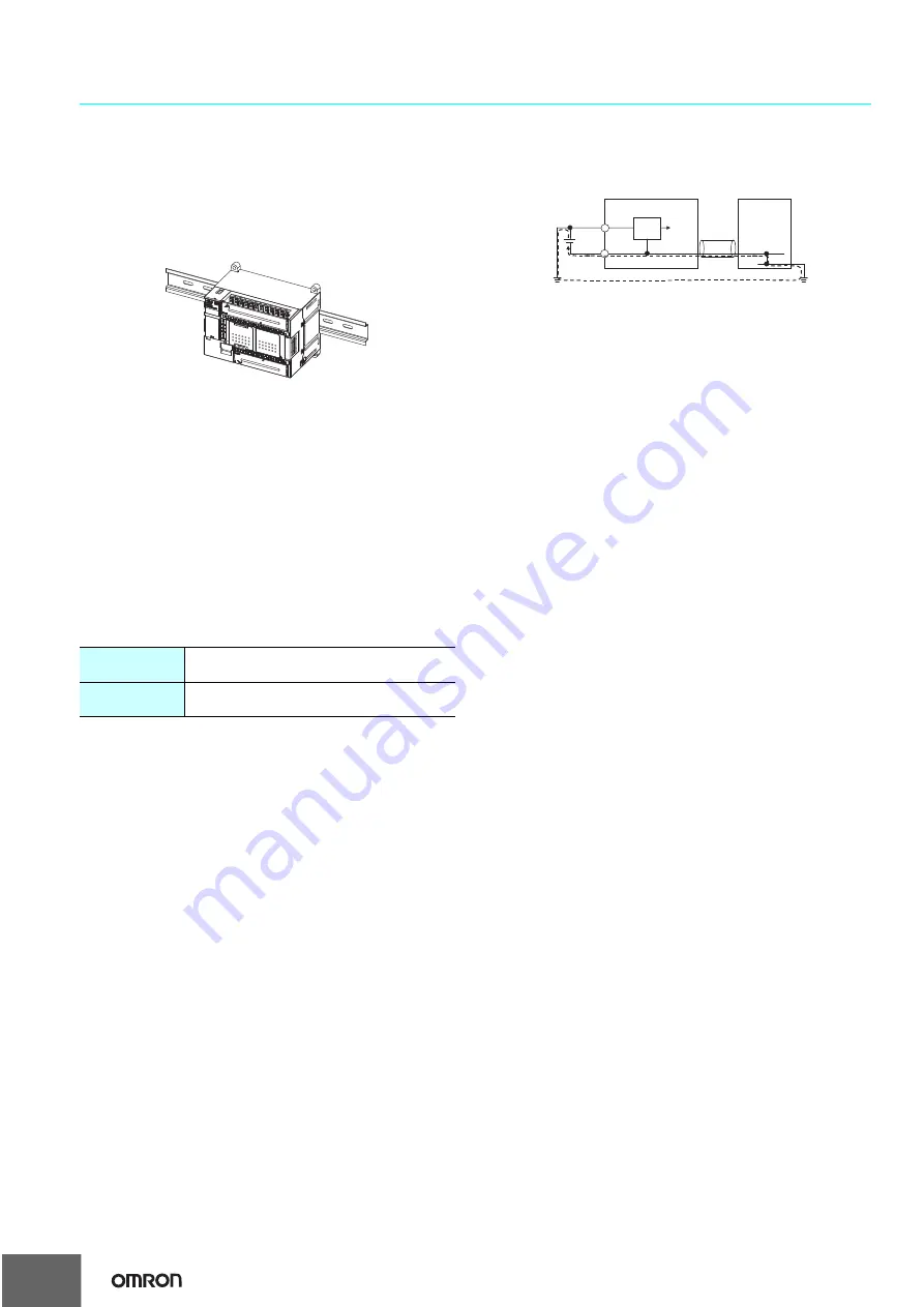
• Do not ground the 24-V side of the power supply to the G9SP-
series Controller. If you do so, an unwanted current flow shown in
the following diagram may occur when you connect a computer or
other peripheral device.
• Do not connect the Expansion I/O Units over the specified number.
Power Supply Selection
Use a DC power supply satisfying the following requirements.
• The secondary circuit of the DC power supply must be isolated
from the primary circuit by double insulation or reinforced insula-
tion.
• The isolated power supply with a current limited to 8 A.
• The output hold time must be 20 ms or longer.
• The DC power supply must be an SELV power supply that sat-
isfies the requirements of IEC/EN 60950-1 and EN 50178.
Periodic Inspections and Maintenance
• Disconnect the G9SP-series Controller from the power supply
before replacing the Controller. Devices connected to the G9SP-
series Controller may operate unexpectedly.
• Do not disassemble, repair, or modify the G9SP-series Controller.
Doing so may lead to loss of safety functions.
Disposal
• Be cautious not to injure yourself when dismantling the G9SP-
series Controller.
Solid wire
0.32 to 0.82 mm
2
A
W
G22 to A
W
G18
0.32 to 0.5 mm
2
A
W
G22 to A
W
G20
*
Stranded wire
0.5 to 1.3 mm
2
A
W
G20 to A
W
G16
0.5 to 0.82 mm
2
A
W
G20 to A
W
G18
*
DC power circuit
24 V
0 V
0 V
0 V
G9SP
Peripheral device
GND
USB cable
FG
16


