background image

Setup Mode

Section 4-5

40

4-5-3-4 

Read_Actual_Configuration

Function

Read  the  ID  code  and  I/O  code  of  an  actual  slave  connected  to  the  AS-
Interface line.

Command Code

5 (

0101

)

Command Argument 1

Slave address (2 digits BCD).

Command Argument 2

Not required.

Command Status

1

Command processed, and Return Value is valid.

2

Error in processing the command
(invalid argument value or Slave read error).

other

Master is busy.

Actual Configuration Data for slave [Command Argument 1].
1 byte hexadecimal code, representing I/O Code and ID Code.

15 14 13 12 11 10 9

8

7

6

5

4

3

2

1

0

  IR n

0

0

0

1

1

Setup Mode

Command Status = OK

I/O Code

ID Code

Command Return Value

See Appendix B, AS-Interface Slave Profiles, for a list of ID codes and I/O
codes.

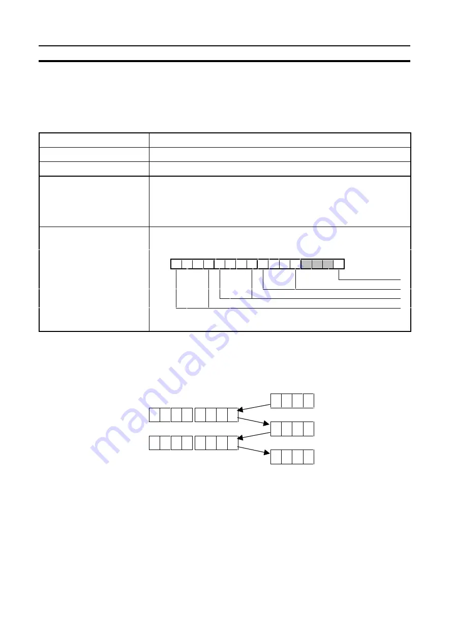
Example

Try to read the configuration data of the (non-existing) slave with address 18.

Command

IR101          IR100

Response

IR001

X X X D Master in Setup Mode

Send ’No_Command’

-

-

-

-

-

-

0 2

(X = previous data)

0 0 0 D Master Ready

Send Command

-

-

-

-

1 8 5 2

0 0 2 D Command Error

Slave not detected

Summary of Contents for CQM1-ARM21

Page 1: ...CQM1 ARM21 AS Interface Master Unit OPERATION MANUAL Cat No W357 E1 1...

Page 2: ......

Page 3: ...CQM1 ARM21 AS Interface Master Unit Operation Manual Produced April 1999...

Page 4: ...iv...

Page 5: ...Wd in documentation in this sense The abbreviation PLC means Programmable Logic Controller and is not used as an abbreviation for anything else Visual Aids The following headings appear in the left c...

Page 6: ...vi...

Page 7: ...NS AND PERFORMANCE 17 3 1 Overall Specifications 18 3 2 Dimensions 19 3 3 Performance 19 4 PLC INTERFACE 25 4 1 PLC Settings 26 4 2 Internal Data Structures 27 4 3 Master Operation Modes 28 4 4 AS Int...

Page 8: ...viii...

Page 9: ...allation of the CQM1 ARM21 Section 3 describes the overall specifications and the communication performance of the Unit Section 4 describes the interface with the user Section 5 describes how to set u...

Page 10: ...x...

Page 11: ...tant for the safe and reliable application of the AS Interface Master Units You must read this section and understand the information contained before attempting to set up or operate an AS Interface M...

Page 12: ...e to provide the systems machines and equipment with double safety mechanisms This manual provides information for installing and operating OMRON AS Interface Master Units Be sure to read this manual...

Page 13: ...removing any Units e g I O Units CPU Unit etc or memory cassettes Assembling any devices or racks Connecting or disconnecting any cables or wiring Failure to abide by the following precautions could l...

Page 14: ...en signal lines or momentary power interruptions Provide external interlock circuits limit circuits and other safety circuits in addition to any provided within the PLC to ensure safety 6 EC Directive...

Page 15: ...ace This section provides a general introduction to AS Interface 1 1 Introduction 2 1 1 1 AS International 2 1 1 2 System Components 3 1 1 3 Technical Details 4 1 2 Master Functionality 7 1 3 Slave Fu...

Page 16: ...available from 30 vendors OMRON is a full member of the AS International Association Positioning AS Interface is primarily aimed at the transfer of binary in and output data in industrial applications...

Page 17: ...4 inputs 4 outputs 248 The slave s circuitry is generally powered via the AS Interface line but in and output ports may have a provision for external power supply Power Supply Superimposing communicat...

Page 18: ...AND exchange I O data with slave stations over a simple unshielded two wire cable To achieve this while maintaining reliability and electromagnetic compatibility in an industrial environment a specif...

Page 19: ...posed of the following elements Start bit Control bit 5 Bit Address 5 Bit Information Parity bit End bit ST 0 CB A4 A3 A2 A1 A0 I4 I3 I2 I1 I0 PB EB 1 Response After each master request the master wil...

Page 20: ...he list of active slaves The master will cyclically try to re initialise the slave in the inclusion phase Performance The cycle time of an AS Interface network depends on the number of slaves that the...

Page 21: ...sists of the M0 profile plus 2 additional functions to set and store slave parameters The CQM1 ARM21 provides M0 functionality in standard operation mode but additional configuration functions are ava...

Page 22: ...sensor or other devices and elements Thus the profiles should help to increase the interchangeability of actuators and sensors A slave profile has a well defined and fixed I O configuration I O code w...

Page 23: ...nstall an AS Interface system 2 1 Physical Layout of the Unit 10 2 1 1 Front Cover 10 2 1 2 LED Indicators 11 2 1 3 Switches 12 2 1 4 Connector 14 2 2 Mounting the CQM1 ARM21 14 2 3 AS Interface Netwo...

Page 24: ...re the same as those of comparable CQM1 I O units For mounting instructions see the CQM1 Operation Manual The front of the unit features A removable front cover 23 LED indicators for unit status bus s...

Page 25: ...ine is too low to guarantee reliable communication CER red Configuration error ON The detected actual configuration is different from the stored projected configuration AUP yellow Auto programming is...

Page 26: ...on with more than 15 slaves this indicator will periodically turn OFF and ON to show the status of all slaves If set to 15 or fewer slaves this LED will remain OFF 2 1 3 Switches CH The switches 1 3 s...

Page 27: ...BUS error in the CPU RSV Reserved Keep this switch in OFF position MOD Selects the operation mode of the AS Interface master OFF Configuration Mode Setup Mode In Configuration Mode the AS Interface ma...

Page 28: ...Unit connect it to a CQM1 PLC just like other Units such as I O Units Refer to the PLC s Operation Manual for details on mounting Units to the PLC or installing the PLC in a control panel A label is s...

Page 29: ...rated AS Interface slave function A hand held addressing device can be useful to build up the network but is not essential since the CQM1 ARM21 provides equivalent functionality when used in Setup Mod...

Page 30: ...AS Interface Network Installation Section 2 3 16...

Page 31: ...tion describes the overall specifications and the communication performance of the CQM1 ARM21 3 1 Overall Specifications 18 3 2 Dimensions 19 3 3 Performance 19 3 3 1 AS Interface Cycle Time 20 3 3 2...

Page 32: ...words out Max No of Slaves per Master Unit Switch selectable With minimum IR words 11 slaves With maximum IR words 31 slaves Status information in PLC Operation Mode flag System Error flag Normal Ope...

Page 33: ...etween the change of state of a data bit in the PLC memory and the moment that the corresponding output on a slave unit changes state Since AS Interface is an open bus system it is possible to use sla...

Page 34: ...the next data exchange phase 0 168 ms after the start of the inclusion phase The 0 154 ms is the time taken by each master request slave response and the pauses in between The exact value of course de...

Page 35: ...g seviced tMP1 Master processing time Start receiving slave response data available at the I O bus tRF I O refresh time Time required to update inputs and outputs of all CQM1 I O units tPE Program Exe...

Page 36: ...s tRF I O refresh time Time required to update inputs and outputs of all CQM1 I O units tPE Program Execution time Processing of the PLC program and peripherals tPLC PLC Cycle time scan time tPE tRF t...

Page 37: ...3 3 23 Optimisation The processing time in the PLC can be reduced by using the IORF instruction in the PLC program Interrupt input refresh Direct output refresh See the CQM1 CPM1 Programming manual W...

Page 38: ...Performance Section 3 3 24...

Page 39: ...ags 31 4 4 2 Control Bits 32 4 4 3 I O Data Bits 33 4 5 Setup Mode 34 4 5 1 Command Area 34 4 5 2 Response Area 36 4 5 3 Commands 37 4 5 3 1 No Command 37 4 5 3 2 Get_Permanent_Configuration 38 4 5 3...

Page 40: ...4 EV1 NL CQM1 CPU45 EV1 NL Produced after 01 04 1999 at OMRON Manufacturing of the Netherlands Lot No 01 4 9 N With the above models support for the CQM1 ARM21 s I O range can be activated by setting...

Page 41: ...data from the inputs of all active slaves Input data of inactive slaves is set to zero 0 LDS List of Detected Slaves In this list one bit is set for each slave 0 31 that is detected by the master thro...

Page 42: ...s is set to default values FH PP Permanent Parameter This array contains the configured parameters of all slaves 1 31 created either by local configuration of the master using Set_Permanent_Parameter...

Page 43: ...lave means a slave with its address set to 0 and the same type means with identical ID code and identical I O code This process is called Auto programming When the master detects one missing slave whi...

Page 44: ...As a result all slaves will temporarily be reset Setup Mode Setup mode is not defined by the AS Interface Specification In Setup Mode the CQM1 ARM21 does not comply with the requirements of an AS Inte...

Page 45: ...input word allocated to the Unit is indicated as IR n n 001 006 The first output word allocated to the Unit is indicated as IR m m 100 106 The Status Flags are inputs to the PLC Host system that indic...

Page 46: ...anent configuration data 4 4 2 Control Bits IR m 00 Auto_Address_Disable Bit 0 Auto Addressing is enabled When the AS Interface master is in Protected Mode it is possible to replace slaves on line by...

Page 47: ...lave 23 Slave 22 Slave 21 Slave 20 Inputs from slaves 20 23 IR n 6 Slave 27 Slave 26 Slave 25 Slave 24 Inputs from slaves 24 27 IR n 7 Slave 31 Slave 30 Slave 29 Slave 28 Inputs from slaves 31 28 D3 D...

Page 48: ...figure an AS Interface system without the necessity of additional configuration tools Functions accessible to the user only in Setup Mode are Reading and writing of the permanent configuration data in...

Page 49: ...and Code to 0 prepares the master for the next command Command Code 0 MUST be issued before each command 1 Get_Permanent_Configuration Returns the master s permanent configuration data for one slave a...

Page 50: ...ord allocated in the CPU will contain the master s response to a command in addition to the status flags IR n 00 IR n 03 Status Flags See 4 4 1 Status Flags IR n 04 IR n 07 Command Status 0 No command...

Page 51: ...make sure that the Mode Flag is ON before a command is sent If the Mode Flag is OFF e g due to the MOD switch forcing the unit to stay in Protected Mode switch ON the master will interpret the comman...

Page 52: ...error other Master is busy Permanent Configuration Data for slave Command Argument 1 1 byte hexadecimal code representing I O Code and ID Code 15 14 13 12 11 10 9 8 7 6 5 4 3 2 1 0 IR n I O ID 0 0 0 1...

Page 53: ...1 0 Command Argument 2 IR m 1 I O ID ID Code I O Code See Appendix B AS Interface Slave Profiles for a list of ID codes and I O codes Command Status 1 Command processed 2 Error in processing the comma...

Page 54: ...Master is busy Actual Configuration Data for slave Command Argument 1 1 byte hexadecimal code representing I O Code and ID Code 15 14 13 12 11 10 9 8 7 6 5 4 3 2 1 0 IR n 0 0 0 1 1 Setup Mode Command...

Page 55: ...nd Status 1 the command was processed successfully If not the following flags indicate the type of error 15 14 13 12 11 10 9 8 7 6 5 4 3 2 1 0 IR n 0 0 1 0 1 Setup Mode Command Status Error Slave not...

Page 56: ...No_Command 0 2 X previous data 0 0 0 D Master Ready Send Command 3 1 2 3 7 2 0 0 1 D OK Example 2 Change the address of slave 1 to 31 while slave 31 already exists on the network Command IR101 IR100 R...

Page 57: ...command invalid argument value or EEPROM read error other Master is busy Permanent Parameter Data of slave Command Argument 1 4 bits as below 15 14 13 12 11 10 9 8 7 6 5 4 3 2 1 0 IR n P3 P2 P1 P0 0 0...

Page 58: ...1 0 IR m 1 P3 P2 P1 P0 Parameter Data Command Argument 2 The meaning of Parameters P0 P4 is slave specific Command Status 1 Command processed successfully 2 Error in processing the command invalid arg...

Page 59: ...rgument value or Slave read error other Master is busy Permanent Parameter Data of slave Command Argument 1 4 bits as below 15 14 13 12 11 10 9 8 7 6 5 4 3 2 1 0 IR n P3 P2 P1 P0 0 0 0 1 1 Setup Mode...

Page 60: ...nt value or Slave write error other Master is busy Result of the Write_Parameter Command error flag If all error flags are off and Command Status 1 the command was processed successfully If not the fo...

Page 61: ...ile the switches can be operated locally If the MOD switch is set from OFF to ON while in Setup Mode the ERR LED will light to indicate that the requested mode change could not be made The user is to...

Page 62: ...Setup Mode Section 4 5 48...

Page 63: ...complete AS Interface network 5 1 AS Interface Set up Methods 50 5 2 Bottom up Method 50 5 2 1 Bottom up with addressing unit 50 5 2 2 Bottom up without addressing unit 51 5 3 Top down Method 51 5 3 1...

Page 64: ...k will be stored as projected configuration and once in Protected Mode the master will communicate with all these slaves even if slaves of the wrong type or the wrong address have been installed In th...

Page 65: ...e safest way to set up the AS Interface network The projected slave configuration can be defined in advance and stored in the master unit When installing the system the user can easily verify if the a...

Page 66: ...o address 0 they need to be added and re programmed one by one 1 2 3 1 Connect the AS Interface cable and power supply to the CQM1 ARM21 2 Put the master in Setup Mode MOD switch OFF Mode bit IR m 01...

Page 67: ...ce operations needed to keep the AS Interface Master Unit operating properly 6 1 Error indicators 54 6 2 Troubleshooting 54 6 2 1 PLC Errors 54 6 2 2 Start up Problems 55 6 2 3 Configuration Problems...

Page 68: ...o indicate that its initialisation could not be completed Symptoms Possible cause Possible remedy An I O unit or the end cover is not connected properly Turn the PLC s power OFF and check for loose un...

Page 69: ...pplies from standard types 6 2 3 Configuration Problems When encountering problems during the configuration of an AS Interface network check the table below Symptom Possible cause Possible remedy CER...

Page 70: ...alfunctions or bad connections Error response to a Setup Mode command affecting actual slaves Slave address is above the limit set by the CH switches Use only slave addresses within the range selected...

Page 71: ...ta exchange with the slave via the allocated IR bits If necessary replace the slave Slave status LED is flashing Slave 0 LED flashing indicates that a slave with address 0 is detected Assign a valid a...

Page 72: ...dition In general inspect the system once every 6 to 12 months but inspect more frequently if the system is used with high temperature or humidity or under dirty dusty conditions Inspection Equipment...

Page 73: ...ction contains additional information concerning AS Interface specifications and terminology Appendix A AS Interface PICS 60 Appendix B AS Interface Slave Profiles 63 Appendix C AS Interface terminolo...

Page 74: ...ist31 13 Status List31 Get_LPS 14 Status List31 Get_LAS 15 Status List32 Get_LDS 16 0 Status Flags Get_Flags 16 1 Status Flag Get_Flag_Config_OK X CER LED Status Flag n 03 2 1 2 4 4 1 16 2 Status Flag...

Page 75: ...ED Status Flag n 03 2 1 2 4 4 1 16 2 Status Flag Get_Flag_LDS 0 16 3 Status Flag Get_Flag_Auto_Address_Assign 16 4 Status Flag Get_Flag_Auto_Prog_Available X AUP LED 2 1 2 16 5 Status Flag Get_Flag_Co...

Page 76: ...62...

Page 77: ...virgin R reserved Defined slave profiles exist for I O X ID F Free profiles I O X ID 0 Remote I O ports I O 0 ID 1 Two dual signal sensors I O 3 ID 1 One dual signal sensor one dual actuator I O 8 ID...

Page 78: ...face line and capable to communicate properly address assignment Replacement of the existing address of the AS Interface slave with a new address address An address out of the address space of the AS...

Page 79: ...the master The list is available in the master list of detected slaves A list of all slaves actually detected by the master The list is available in the master list of projected slaves A list of all c...

Page 80: ...66...

Page 81: ...ication Problems 57 Specification See Specification AS Interface Configuration Functions 18 35 Mode See Mode Network 50 52 Problems 55 Store 13 50 52 Connector 14 18 Control Bits 32 Auto_address_disab...

Page 82: ...e Mode R Response area 36 Response time 19 21 Retransmission 20 RSV See Switches RUN See Indicators S SET See Switches Setup Mode See Mode Slave Address 3 Indicators 12 IO ID codes Profiles 3 8 29 63...

Page 83: ...catalog number on the front cover of the manual Cat No W357 E1 1 Revision code The following table outlines the changes made to the manual during each revision Page numbers refer to the previous versi...

Page 84: ......

Page 85: ...Regional Headquarters OMRON EUROPE B V Wegalaan 67 69 NL 2132 JD Hoofddorp The Netherlands Tel 31 0 23 568 1300 Fax 31 0 23 568 1388...

Page 86: ...Authorized Distributor Cat No W357 E1 1 Note Specifications subject to change without notice Printed in the Netherlands...

Reviews: