background image

8

03 - Installation & setup

3.1  Installation checklist

The installation of the system will include the following tasks:

1.  Planning your system setup
2.  Prepared all required tools and items
3.  Site the individual equipment
4.  Route the cables
5.  Create the opening for the Joystick Controller
6.  Drill the mounting and cable holes for Camera Turret
7.  Connect the cables to the products
8.  Secure all products in place
9.  Power on and test the system
10. Perform cable management

3.2 Layout & location

Before you commenced the installation, it is important to produce a schematic diagram. The 
diagram will be handy for any future maintenance or upgrades to the system. The diagram 
should include the location of all components, cable types, routing and length.

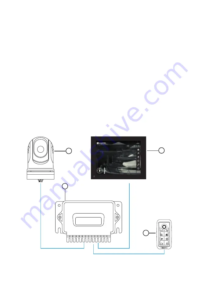
This is the layout plan of how your Ulysses Micro thermal camera system will be set-up.

4

1

3

2

1. Camera Turret
2. Junction Box
3. MFD
4. Joystick Controller (if purchased)

Summary of Contents for ULS-M384S

Page 1: ...User Manual Part No ULS M384U ULS M384S ULS M640S Ver 3 1 High performance compact thermal camera...

Page 2: ......

Page 3: ...urchased 13 3 6 Connecting to your display options 14 3 6 1 Connecting to your MFD 14 3 6 2 Connecting to an analog monitor 15 3 6 3 Connecting to a laptop desktop 16 3 7 Cable management 16 04 Operat...

Page 4: ...5 4 Video 32 5 5 5 Position 33 5 5 6 Function 36 5 5 7 Controller 38 5 5 8 Junction Box 40 5 5 9 NMEA 41 5 6 Home Standby 42 06 Joystick Controller 43 07 Maintenance 45 7 1 Caring for the camera 45 7...

Page 5: ...apment hazard This product features moving parts that may pose potential hazards for entrapment Keep clear of moving parts at all times Ensure safe navigation This product is intended only as an aid f...

Page 6: ...erein are used for identification only and are the property of their respective owners Due to our policy of continuous product improvement Omnisense Systems reserves the right to change the specificat...

Page 7: ...This manual will provide you with all the information you will need for installation and to familiarize yourself with the functions 2 1 Document information This document contains relevant informatio...

Page 8: ...2 4 Installation tools requirements The following are additional tools and items required for installation that are not included in the package 1 Drill 2 Jig Saw 3 Drill bit 0 27in 7mm 4 Drill bit 0...

Page 9: ...a controls and displays You may find it helpful to bookmark this section and refer to it as you read through the rest of the manual Mounting Base Base Detachable Cover Turret pan 360 Camera tilt 100 9...

Page 10: ...cables to the products 8 Secure all products in place 9 Power on and test the system 10 Perform cable management 3 2 Layout location Before you commenced the installation it is important to produce a...

Page 11: ...for periodic cleaning fresh water rinse an inspection of mounting point integrity mechanical soundness and preventive maintenance Camera Turret mounting point should be sturdy and free from excessive...

Page 12: ...l 2 Using the Mounting Template or Mounting Decal provided mark and drill the 0 27in 7mm holes required for attaching the Camera Turret 3 Place your Camera Turret base over the screw holes and secure...

Page 13: ...ning fasteners and the polycarbonate cover Create necessary openings for cables on the weather rubber seal found at the cable seat Once cabling connections are completed replace the polycarbonate Junc...

Page 14: ...wer cable consists of one inner black and white wire Please ensure that the correct polarity is inserted into the right terminal Black for negative White for positive 6 NMEA 0183 socket Your Ulysses M...

Page 15: ...ile thumb and index fingers move the knob 1 The Joystick Controller has a flush back that can be easily fitted onto any flat surface Select a suitable location close to your MFD Monitor 2 Using the Jo...

Page 16: ...UI is for Garmin MFD If you are using a Garmin s MFD you should see a Ulysses Micro icon on the display after powering up both the MFD and camera system Launch the Ulysses Micro icon to access the UI...

Page 17: ...onitor 1 Connect the AV analog cable from the AV port in the Junction Box to your analog monitor 2 The display will appear on the screen Use the Joystick Controller to control the camera 3 For this se...

Page 18: ...o the User Interface UI on your web browser you can control and access the camera settings by using the mouse on your laptop desktop laptop 3 7 Cable management Cable routing must be conducted correct...

Page 19: ...s powered on 3 The Camera Turret will park the sensor lens down into park position when in Standby mode 4 When your Camera Turret is mounted in the ball up upright position the sensor lens will face d...

Page 20: ...elect OK on the dialog box to confirm If gyro calibration is unsuccessful a Gyro calibration unsuccessful message will be displayed To perform gyro calibration again select Calibrate on the dialog box...

Page 21: ...thermal images 1 Consider every object you view in terms of how it will look thermally as opposed to how it looks to your eye For example look for changes caused by the heating effect of the sun Thes...

Page 22: ...b browser Use your mouse to click anywhere on the screen to display the Quick Menu and the Virtual Joystick If you are using an analog monitor Install the Joystick Controller to access the camera see...

Page 23: ...ual Joystick To direct or point the camera to the intended direction and or object Select and drag the middle button on the Virtual Joystick towards the intended direction Function Quick access functi...

Page 24: ...r if purchased controls all panning and tilting operations of your Turret and Camera Use the Virtual Joystick or Joystick Controller to pan turn left or right and tilt up or down the camera to search...

Page 25: ...alettes See section 5 1 for more details Zoom Zoom level from 1 0 to 4 0X See section 5 2 for more details Brightness Contrast Adjust image brightness and contrast See section 5 3 for more details Rad...

Page 26: ...up or down Colour Feature White Hot Light colors for hotter objects regions Default mode for the IR display Black Hot Inverted version of White Hot Dark colors for hotter objects regions Highlight Sel...

Page 27: ...sensor with the ability to zoom into target objects up to 4 0X magnification Select to activate the zoom slider Move the slider to the left or right to control the amount of magnification Tap or clic...

Page 28: ...ng temperature and environment As the heat emitting from the camera can interfere with its performance the NUC function allows the camera to adjust the image based on its own IR radiation readings The...

Page 29: ...al changes to the vessel The imbued gyro stabilization technology counteracts excessive ship motion caused by wave actions or vessel movement ensuring the image quality remains crisp and clear To acti...

Page 30: ...Track function Select target from the radar on your Multi function Display MFD The camera will slew to the selected direction and the target will be shown on the display if the target is within the pe...

Page 31: ...3 Video 4 Position 5 Function 6 LED 7 Controller 8 Junction Box 9 NMEA 5 5 1 Information The Information section provides an overview of the camera system configuration Camera S N Camera IP Junction B...

Page 32: ...set to pair with a Garmin s MFD by default If you are using Furuno or Navico s MFD you can set the IP address automatically to pair with one of the supported brands using the preset button To change...

Page 33: ...ct with other devices in your network To change the IP address settings 1 Select on the IP field IP Address Subnet Mask or Gateway that you wish to change 2 Enter the preferred IP address 3 Select Sav...

Page 34: ...ave Reboot Select OK on the dialog box to confirm 3 After the reboot the video output will be displayed with the new format Bitrate If you re having trouble with video quality adjust the bitrate using...

Page 35: ...ect either Ball up with the Camera unit mounted upright or Ball down with the Camera unit upside down 1 Select on the appropriate orientation Ball Up or Ball Down 2 Select Save Reboot Select OK on the...

Page 36: ...tilt position of the camera when the Home option is activated To utilize this function 1 At the Set Home Position field select Set 2 Pan and tilt the camera to your preferred Home position 3 Select to...

Page 37: ...ttings To reset the Home position to factory default 1 At the Reset Home Position field select Set once 2 Select OK on the dialog box to confirm 3 The original position is set to factory default Camer...

Page 38: ...y detect the camera and display the Ulysses Micro icon on the screen You can launch the Ulysses Micro user interface UI by tapping clicking on the icon Do not turn off this function unless it s necess...

Page 39: ...color preset For customization of the lighting s color select the last color icon and adjust the slider for Red Green and Blue accordingly To change the brightness of the LED simply shift the slider f...

Page 40: ...Controller that is connected to the system Once the Joystick Controller is found the serial number will be displayed Select to connect the Joystick Controller and it will be ready for use If the syste...

Page 41: ...If the Joystick Controller s IP address is causing conflict with other equipment in the network you can change the IP address manually To change the IP address 1 Select on the IP address field and en...

Page 42: ...other Junction Boxes that may have been connected to the system use the arrow to scroll through other Junction Box if connected The enabled disabled the camera to acquire the radar track coordinates o...

Page 43: ...nt through NMEA 2000 Ethernet connection This allows you to activate the Slew to Cue capability of the camera system To activate the function slide to the right NMEA Server If the IP address of the NM...

Page 44: ...face down ball up or face up ball down Home Standby Home To return turret to home position select Home To reset or set a new home position see section 5 5 5 Standby To set turret in park position sele...

Page 45: ...menu items Use the joystick to select and cycle through the options available Function Programmable key Enter Confirm selection Menu Display menu options Zoom Adjust zoom Sensor Select Toggle between...

Page 46: ...unt of zoom See section 5 2 for more details Sensor Select Toggle between thermal and day cameras Not available for Ulysses Micro Home Standby See section 5 6 for more details Track Radar Tracking or...

Page 47: ...amera and controller firmly at the base to confirm that it is secured soundly Do not leave the lens pointed at the sun Do not leave or park the lens pointed at the sun or other strong light sources fo...

Page 48: ...on Box is drawing excessive power more than 28W The system will cut off all power to the equipment connected to it and automatically reset Note Only products from the camera system are certified to be...

Page 49: ...s Perform this action for a total of 4 times On the 5th time keep the system power up and you should be able to operate the camera system Note The camera turret IP will be reset to the factory default...

Page 50: ...S 384 X 288 384 X 288 640 X 480 29 H X 22 V 24 H X 18 V 24 H X 18 V N Y Y 13mm 17um Uncooled Microbolometer LWIR FPA Continuous E Zoom 1 0X 4 0X Pan Continuous 360 Tilt 100 90 Composite Analog Video O...

Page 51: ...49...

Page 52: ...omnisense systems com Omnisense Systems USA Inc 1881 West State Road 84 Bldg 1 Unit 102 Fort Lauderdale Florida 33315 United States T 1 954 316 6230 E enquiries omnisense systems com...

Reviews: