


19
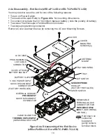
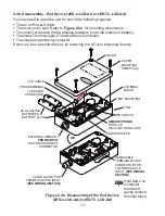
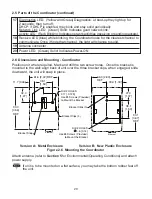
2.5 Parts of the Coordinator
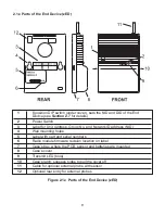
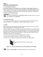
Figure 2.5 Parts of the Coordinator
1
Wall mounting bracket clip holes (3 places)
2
Label with part and serial numbers
3
Coordinator’s firmware revision on label
4
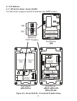
8 position DIP switch, from which the last 3 positions are used to assign the NID,
network ID number (see
Section 2.7
for details)
5
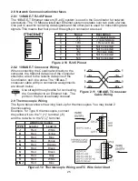
Ethernet: RJ45 interface for 10BASE-T connection.
6
Case’s tray, where the PCB is mounted
7
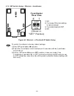
4 position DIP switch, sets the DHCP and Factory Defaults
8
Coordinator’s radio module firmware revision on label
9
Label with default IP address, remove and then write your IP address, in the space
provided
10
Label with MAC address (in hex code)
11
Wall mounting bracket
12
Case’s cover mounting screw (2 places)
13
Label for Network ID address (NID)
14
Power supply: Plus (+) power supply wire connection inside the plug;
Minus (-) power supply wire connection outside the plug
15
Reset button: Used for power reseting the Ethernet board
16
Case’s cover


