


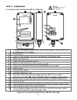
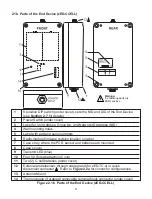

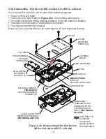
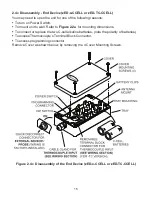


2.1b Parts of the End Device (zED-CCELL)
1
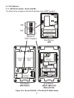
8 position DIP switch (under cover), sets the NID and DID of the End Device
(see
Section 2.7
for details)
2
Power Switch (under cover)
3
Label for Unit Address, Group No. and Network ID Address (NID)
4
Wall mounting holes
5
Label with part and serial numbers
6
Radio module firmware revision location on label
7
Case’s tray, where the PCB, sensor and batteries are mounted
8
Case’s cover
9
Transmit LED (blue)
10
Four (4) Screws attaching Cover
11
Two (2) C-cell batteries (under cover)
12
External probe/sensor, through cable gland (for zED-TC-x) or quick
disconnect connector . Refer to
Figure 2.2a
for connector configurations.
13
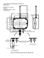
Antenna Mount
14
Thermocouple (if ordered) removable terminal block connector (under cover)
Figure 2.1b Parts of the End Device (zED-CCELL)
6
Warning:
the following parts are
ESD sensitive.


