background image

AWS Installation and operating manual 


www.omega-air.si 

Electrical connection 


Only  qualified  personnel,  is  allowed  to  set  up  the  electrical  connection.  Prepare  the  main 
plug with the main switch and a proper fuse (or circuit-breaker) for the electro connection of 
the equipment. Grounding is mandatory. Before the start-up check all the connections and 
fix  them if necessary.  Before  you  connect the  compressor  to  el. power,  check  if the power 
supply is compatible with the power requirement of the system. If that is not the case, heavy 
damage can occur, which may render the warranty null and 
void.  

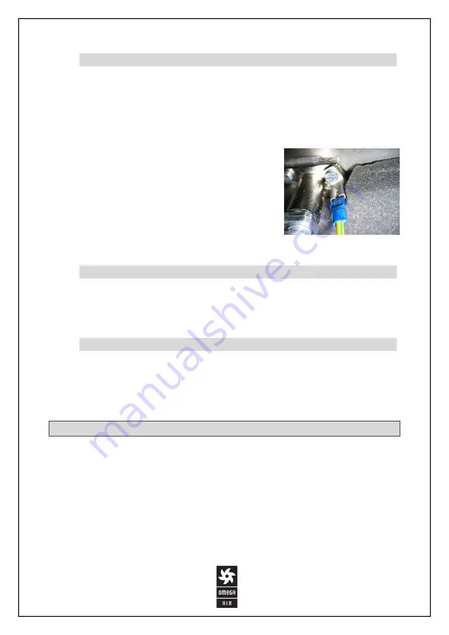
Check  the  system,  if  the  grounding  is  as  required  by 
regulations.  Connect  the  compressor  on  the  power  supply 
and  do  not  use  any  inappropriate  extensions,  which  may 
damage the compressor. Do not do any repairing or changes 
and  do  not  cut  or  damage  the  cables.  If  the  cable  for  the 
energy supply is damaged, replace it with a new one of the 
same type. Always attach the grounding connections on the 
housing as required.  

Water connection 


The system has to be connected to a water supply with a hose of at least 50cm in length. The 
hose  needs  to  be  of  appropriate  size  and  in  accordance  with  the  supply  connector  the 
connector on the housing.  

Condensate drain connection 


The condensate drain connection to the drain pipe goes by a flexible hose, at least 50cm of 
length.  The  hose  has  to  be  of  appropriate  dimension  in  accordance  with  the  connector  on 
the condensate drain and the dimensions of the pipe for the drain.   

Launch 

Before  activating  the  equipment,  there  are  a  few  checks  necessary  (follow 
thoroughly): 


Check the oil level in the compressor with the help of the oil indicator (picture 4)  


The  red  dot  in  the  middle  marks  the  ideal  oil  level  (if  the  oil  level  is  inappropriate, 
check the maintenance) 


Check if the condensate drain, located on the bottom of the filter (pressure vessel), is 
closed (picture 5) 


Check if the button on the pressure switch is OFF – 0. 


Picture 3: Grounding


Summary of Contents for AWS

Page 1: ...stallation and operating manual AWS Please read the manual thoroughly before putting the unit into service Only if you follow and respect the directions and advice provided by the manual can we ensure safe and reliable operation of the unit ...

Page 2: ...lation operation disassembly Our personnel are available for any further information and explanation As the manufacturer of the equipment we decline any responsibility for malfunctions which might occur through improper interpretation of the manual unprofessional installation or failure to comply with valid standards and regulations by law EQUIPMENT PRESENTATION The AWS equipment is a comprehensiv...

Page 3: ...ecuted by properly qualified personnel When working with the equipment the user is also obliged to follow all the local safety regulations and regulations for accident prevention if any such exist LOCATION REQUIREMENTS The AWS equipment is not protected against explosions and as such it must not be installed in a dangerous environment The surface where the equipment is supposed to stand has to be ...

Page 4: ...o find any possible faults INSTALLATION AND CONNECTION Preparing the place for installation and assembly Example of the basis Picture 1 Dimensional drawing of the AWS basis At the basis if there is a shaft a steel construction is advised contact the manufacturer The preparation of an appropriate basis is shown in the attachment When setting up the foot of the equipment spacers are mandatory for th...

Page 5: ...r supply cannot be guaranteed with windows or other openings ventilators are required for forced ventilation The ventilators need to guarantee a 15 20 greater amount of cooling air that is needed for perfect cooling of all the compressors ATTENTION The ventilation openings have to be set up in a way to avoid the intake of dust lacquer gasses or other explosive mixtures Do not set the equipment up ...

Page 6: ...upply is damaged replace it with a new one of the same type Always attach the grounding connections on the housing as required Water connection The system has to be connected to a water supply with a hose of at least 50cm in length The hose needs to be of appropriate size and in accordance with the supply connector the connector on the housing Condensate drain connection The condensate drain conne...

Page 7: ... pressure does not reach about 1 bar At this value the valve closes This enables the motor to immediately reach normal rotations and guarantees an optimal start up even in cold weather or tensions under the normal level To turn off the compressor always use the button on the pressure switch If you pull out the plug the compressor head will not release pressure which might cause problems at the nex...

Page 8: ...f a fault on the pressure switch and opens an exhaust for excess air The client may never set the compressor up in any way to exceed the pressure stated on the pressure vessel In the operation time and a few minutes after stopping do not touch any wires connectors compressor parts valve or other parts which may be subjected to excessive heat and avoid burns Pressure in the compressor The pressure ...

Page 9: ...s may though change as a function of conditions in the operation area For regular maintenance properly qualified personnel are required Further information is available at the manufacturer Compressor access To open the equipment follow the steps in picture 7 Picture 7 Access to the compressor in 2 steps The door gets closet following the steps in the opposite direction put the door on the pins pus...

Page 10: ... for compressor heads always available at the manufacturer Do not mix different oils Release the oil through the base of the compressor unit as shown in the picture After emptying close the drain and fill in the required amount of fresh oil After you changed the oil let the compressor work for about 2 minutes then stop the motor and check the oil level again If necessary add more oil Recommended o...

Page 11: ...ases thermal safety regulation Check the oil level and quality if overheating is involved check the performance of all parts Safety valve opening Un configured pressure switch Un configured safety valve Set the pressure switch The safety valve is sealed and very important to the safe operation of the compressor so it is important to replace it with a new one of the same type Hindered start up of t...

Page 12: ...ar The compressor was moved Output tubes on the compressor head cracked Check the bolts and screws Check the compressor unit thoroughly and if necessary change it Strengthen the support on the ground USER INTERFACE FOR TIRE INFLATION ATTENTION The equipment is designed for inflating car tires and is not compatible for inflating bicycle tires with regular valves Ignoring this may cause the bicycle ...

Page 13: ...s Solution Empty LCD screen No electrical power PCB error Check the power supply Call the authorized service After attaching the hose to the tire the pressure correction does not start automatically The pressure in the tire is less than 0 3bar This is a normal case for empty tires to start the pressure correction push the button for inflating flat tires Ω The screen says CHECK THE HOSE There is no...

Page 14: ...1 Dimensions Width A 545mm Depth B 445mm Height H 1550mm Max working pressure 10bar Air flow ISO 1217 250Nl min Pressure tank volume 16 6l Electromotor power 1 5kW Sound level at 1m 68 2dB Voltage 230 V 50Hz Working temperature 15 to 45 C Electric heater power 10W Hose length 8m H A B ...

Page 15: ... Every 1000 hours Condensate drain Check the oil level Check the safety valve Check the belt Check for oil leakage Air filter cleaning Change the air filter cartridge Check the operation efficiency Overall cleaning Oil change Check the belt and transmissions Check the hose tightness Check the electric connection Recommended oil SHELL CORENA P100 ...

Page 16: ...or the mentioned the equipment does not need any additional maintenance Service 24 hours Slovenia OMEGA AIR d o o Cesta Dolomitskega odreda 10 1000 Ljubljana Tel 01 200 68 31 Fax 01 200 68 50 info omega air si www omega air si Croatia CIT d o o Zagreb Ulica grada Vukovara 43 1000 Zagreb Tel 385 1 617 0291 Fax 385 1 617 0385 Mobile 385 99 442 324 Always save this manual for later use The manual is ...

Page 17: ...AWS Installation and operating manual www omega air si 17 ...

Page 18: ...e used The unit was not operated within the permissible technical parameters Unauthorized constructional changes were made to the unit or if the unit has been opened disassembled by an unauthorized person APPENDIX BASIS PREPARATION It is recommended to integrate a steel construction in the basis contact the manufacturer for further information This improves the attachment of the housing to the gro...

Page 19: ...AWS Installation and operating manual www omega air si 19 ...

Page 20: ...AWS Installation and operating manual 20 www omega air si ...

Reviews: