OMAX JetMachining® Center Operator’s Guide
Operation
3 - 10
400433D-EN
material. The bottom of the part being machined is especially vulnerable to slat splash-back and
frosting.
•
Put sacrificial material on material that may delaminate
Cover the top of material that may delaminate during piercing with sacrificial material. This ensures
the abrasive is completely flowing before it reaches the good material.
•
Start at the edge of materials that can’t be pierced
Some materials cannot be easily pierced. For example, weak granites can be pierced, but may chip
or crack apart. When cutting these material types, cuts must be started from an edge of the material.
Other materials, such as glass, can be pierced using low pressure.
•
Avoid material with deep scratches
For the best possible surface finish, use stock that does not have deep scratches on the surface.
Scratches on the surface can deflect the abrasivejet stream and cause irregularities on the bottom of
the part.
•
Draw parts to start in a consistent position
Always design parts so that the starting position is in the same place (such as the upper left-hand
corner). This allows consistent positioning of the abrasivejet nozzle when making parts.
•
Don’t always make parts in the same location
Using the identical location wears out slats in the area more quickly and can cut through the tank.
Make your parts in different areas of the table to even slat wear.
•
Place a rod inside tubing when cutting
When cutting hollow tubing or pipe, place a solid rod inside the tube. In a hollow tube, the abrasivejet
stream spreads out when it strikes the air inside the tube, causing the far end of the cut to be wider
with a ragged edge.
•
The top surface may be used for tooling
The top surface of the OMAX frame is flat and is exactly parallel to the X and Y motion of the
abrasivejet nozzle. This surface may be used for any special fixturing installed.
Note:
For additional tips on effective cutting, consult the OMAX Interactive Reference where an entire section is
devoted to tips.
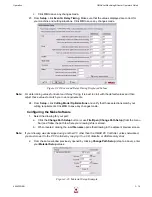
Setting Soft Limits
In the OMAX, there are two types of limits that restrict the area of nozzle movement on a table’s cutting
surface:
absolute
limits (hard) designed into the machine’s hardware and user-defined
soft
limits.
Absolute Limits
define the maximum cutting area that is available on a particular table. These are hardware
limits that are set using physical stops installed on the ends of the ball screw threads for both the X- and Y-
axis (Y=0, X=0 points). Although the cutting head can be commanded to reach these absolute limits, this
seldom is done since this frequently is where the cutting head would crash into the side of the table and
cause serious equipment damage, especially if the crash is done at full speed.
Soft Limits
are defined in software to prevent the cutting head from ever reaching the table’s absolute limits
or to avoid hitting other fixtures placed within the cutting area. These limits can be set to create a smaller
working area within the available maximum cutting area. When a soft limit is reached, a controlled stop is
immediately initiated that prevents further cutting head movement. Whenever a nozzle movement is
commanded that will exceed a defined soft limit, a window pops-up warns the operator that set limits will be
exceeded. When using the keyboard to move the cutting head manually and a soft limit is reached, the
software immediately halts head movement using a controlled slowdown and stop that prevents the nozzle
from exceeding a user-defined soft limit.
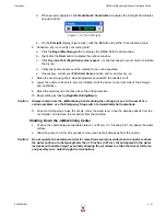
Auto Homing Your Machine
Auto Homing is the process of locating a table’s
Absolute Home
.
Note:
All homes are related to Absolute Home. Absolute home is the only home position that can be lost. Re-
setting Absolute Home resets all other homes to their correct positions.
Summary of Contents for JetMachining Center 2626
Page 8: ...OMAX JetMachining Center Operator s Guide viii 400433D EN ...
Page 12: ...OMAX JetMachining Center Operator s Guide xii 400433D EN ...
Page 22: ...OMAX JetMachining Center Operator s Guide Safety First 1 10 400433D EN ...
Page 140: ...OMAX JetMachining Center Operator s Guide OMAX Glossary 6 16 400433D EN ...
Page 144: ...OMAX JetMachining Center Operator s Guide Index 4 400433D EN ...


